|
U17Sensibly equivalent¶ to:See also:
|
|
|
|
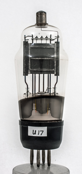
The U17 is an EHT rectifier and suited to providing the anode voltages in CRT based circuits. This exhibit is unmarked but looks to be an M-OV device.An oscilloscope CRT normally has electrostatic deflection plates which, especially in older designs, required quite large signal swings (hundreds of volts) in order to achieve a deflection up to the full screen diameter. It was therefore necessary to provide horizontal and vertical deflection amplifiers capable of very large output voltage swings and this in turn would mean that the deflection amplifiers would require special valves operating from an anode supply of, perhaps, 1,500 V. Additionally, potentiometer chains consuming several mA would be needed to move the zero trace up and down the screen.Since the deflection sensitivity of an electrostatically-deflected CRT varies according to the EHT voltage applied to it, it was essential to use the same rectified supply for the deflection circuits as for the EHT applied to the CRT itself. Thus, the EHT rectifier must supply enough current for two deflection amplifiers and two potentiometer chains in addition to the cathode current of the CRT. With this in mind it can be appreciated that the rectified current rating (30 mA) of the U17 was by no means excessive.As heater-cathode insulation would have posed design problems, the valve is directly heated. The filament passes six times through the anode cavity as a continuous wire making the shape of three inverted V's. The reservoir capacitor can be 1 µF. The normal current for a CRT power supply would be less than 5 mA.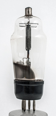
The front to back dimension of the anode box is only 6 mm.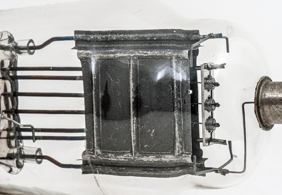
The filament tension springs are held in a composite structure. It consists of an outer metal support enclosing the insulating mica sheet.The classic envelope is 49 mm in diameter and, excluding the B4 base pins, is 122 mm tall.References: Data-sheet & 1040. Type U17 was first introduced in 1936. See also 1936 adverts. |
Pin Connections
| 1 | 2 | 3 | 4 | tc |  nc | nc | f | f | a |
|
|
Absolute Maximum Operating Conditions
| Vh | Ah | Va | mAa | 
| 4.0 | 1 | 2500 | 30 |
|
Updated January 29, 2026.
|
|