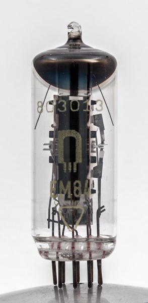
This EM84 valve is in a standard thin glass tube envelope with a phosphor strip on the inside of the glass. The logo is not recognised and thus the make is unknown.
The electrode structure is, like all such tuning indicators, based on a double triode with common cathode. The anode of the second triode is called the target and within the electron stream is a deflector electrode designed to alter the path of the electron beam, it would normally be connected to the anode. In the EM84 the quiescent condition was two green bars, one at each end of the window. As the signal strength increased the bars would elongate and eventually overlap to form a bright green region. The optimum point for tuning was a minimum gap.
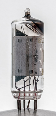
The cathode is on the right. One side points to the screen and the outer side has the triode voltage amplifier. The grid supports can be seen.
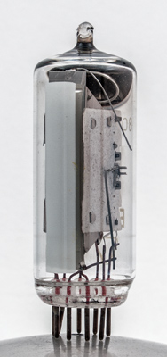
The fluorescence screen with electrodes behind. The grid supports can be seen as two short rods emerging from the side mica sheet.
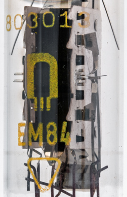
In this enhanced image the logo is clear and we would like to identify this make.
The thin glass tube envelope is 21 mm in diameter and, excluding the B9A base pins, is 58 mm tall.
References: Data-sheet & 1040. Type EM84 was first introduced in 1959. See also1959 adverts.