|
Tuning indicators became necessary when Automatic Volume Control (AVC, aka. AGC) was introduced to domestic radios during the 1930s. Without AVC, tuning a set exactly on to a wanted station was largely a matter of adjusting the tuning knob (or knobs) to obtain the loudest sound and then adjusting the volume control as desired. With AVC, the volume of the detected signal was automatically controlled at the right level so one could no longer tune for maximum sound in order to make sure the set was tuned exactly to the station. The consequence of slight mis-tuning was garbled reproduction and, often, a nasty background whistle if the carrier signal of an adjacent station was too close.
One solution was to provide Automatic Frequency Control (AFC) so that the set automatically pulled itself on to the correct setting. However, while AFC was (and still is) an important facility in radio receivers it has a number of drawbacks. Moreover, in the early 1930s, when AVC and AFC were first introduced, AFC was difficult to implement well. Further, AFC would only work in superhets which at that time were in their infancy, expensive, and often troublesome. AVC, however, was also applicable to straight (TRF = Tuned Radio Frequency) sets which were then the norm.
The principle of (most) AVC systems is that the amplified carrier signal of the station being received is rectified (usually by an auxiliary diode) to provide a negative voltage supply (at very low current). If the carrier signal has been amplified up to a level of, say, 10V then the negative AVC supply created by rectification will be (very roughly) about -10V DC. This negative AVC supply is applied to the RF amplifier (and/or IF) valves in the form of an additional negative grid bias, thus reducing the currents flowing in these valves. As a consequence the valves will give less amplification. For each type of valve there will be some level of negative bias at which the amplification will be reduced to practically zero. When this happens the carrier signal of the station being received can no longer be amplified to 10V (as previously assumed) so the rectified AVC supply will disappear and the valve amplification will increase again. By using vari-mu valves, whose amplification changes smoothly according to the level of AVC bias applied, it is possible to design a set in which the AVC level adjusts itself so that the amplified signal remains quite close to 10V (or whatever level is desired) irrespective of whether the radio station being received is strong or weak (provided, of course, that it is not too weak).
Essentially, then, in an AVC set the amplified signal, and thus the sound heard, may seem to remain at much the same level while the tuning knob is turned through and beyond the correct setting. However, the rectified AVC supply hits a (negative) peak when exactly the right tuning point is reached. The purpose of a tuning indicator is to show when the set has been tuned exactly to this point.
One obvious method is to fit a small panel meter whose needle indicates the magnitude of the AVC negative supply voltage. The user merely has to find the wanted station roughly, using the tuning dial, and then fine-tune the knob for maximum meter reading in order to ensure perfect tuning. This method is still widely used professionally, and by hams (amateur radio operators), particularly as the size of the maximum reading gives useful information about the signal strength; in amateur radio terms the meter is known as an 'S' meter. However, the current available to operate an 'S' meter is typically only a few microamps so a very sensitive meter must be used. In the early 1930s when cheap, robust panel meters typically required several milliamps this was out of the question for popular domestic radios.
It was obvious that the very weak AVC bias voltage would need to be amplified if it was to be indicated in a robust manner. Two methods were available. The first was to use an additional valve amplifier with its output connected to some form of robust, user friendly indicator. This approach led directly to the development of the once-familiar green 'magic eye' indicator. A typical magic eye valve of the late 1930s contained a simple triode amplifier whose grid characteristic was matched to the expected range of AVC bias variation as the set was tuned. The triode amplified the grid variation (say, 10V) to 100V or more at the anode which was internally connected to a control electrode in the green 'eye' at the end of the valve. The large voltage change on this control electrode deflected electrons emitted from the end of the triode cathode (which extended into the centre of the 'eye') and thus altered the shape and position of the green glow which occurred where these electrons landed on a cup-shaped fluorescent 'target' electrode visible through the end of the valve. Correct tuning of the set was thus a matter of finely adjusting the tuning knob so that the glowing area was (typically) maximised.
Except for some teething troubles with the 'eye' section (which in early designs lost its initial brilliance within a few weeks) this was a good solution and was widely adopted in the USA. In Britain, however, there was a problem. Under BVA cartel rules all set manufacturers had to pay a royalty. initially £1 per valve (holder), later 12/6d per valve, for every set sold. Moreover, in order to stop cheating all BVA members had to undertake not to make or sell 'multiple' valves (ie. two or more valve sections in one 'bottle'). The magic eye was clearly an extra valve and arguably two valves!
Added to the cost of providing the tuning indicator in the first place, the extra royalty made the solution unaffordable in popular-priced sets. This, and the fact that triode-hexode frequency changers and double-diode-triode detectors were for a time banned by BVA rules, accounts for the slow introduction of superhets in Britain, long after they had become the norm in America.
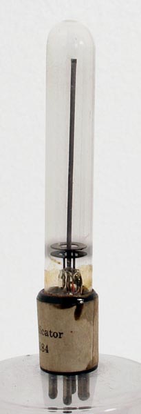
However, enterprising set designers, led by Cossor, fought back by inventing the tuneon of which the type 3184 is an example. Since the neon was not a valve, no royalty was payable. Moreover, the tuneon was much cheaper to make and fit. The problem was that at least 100V was required to operate the neon so amplification of the AVC bias supply was still required. But how?
Simple: A typical RF or AF amplifier stage whose gain was controlled by the AVC bias voltage would (during the early 1930s) use a vari-mu screen-grid tetrode valve. Because of the well-known 'tetrode kink' it was necessary to operate the screen grid at a considerably lower HT voltage (say, 100V) than was applied to the anode (say, 200V in an AC mains set). A convenient way to get 100V from a 200V HT supply is to include a high-value resistor in series with the screen-grid connection to the HT supply. The value of the resistor is chosen so that the voltage drop is 100V (or whatever was appropriate) when the normal screen-grid current is drawn. When negative AVC bias is applied to the signal grid of the screen-grid valve, less current is drawn and the screen-grid voltage therefore rises. Effectively the screen-grid valve amplifies the AVC bias in exactly the same way as the triode section of a magic eye except that the amplified voltage appears at the screen-grid terminal instead of at the anode and no extra valve is required.
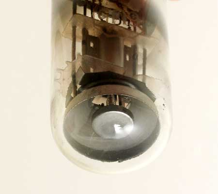
This could be exploited in several ways. The simplest is to connect a neon from screen-grid to HT- so that when the valve draws less current more is left for the neon which therefore glows more brightly. The type 3184 Tuneon is cleverer than this. It has two small ring-shaped electrodes which are tickled with the full HT voltage (through a high-value resistor) in order to 'strike' the neon and maintain ionisation.The long rod is connected to the screen-grid of the valve and draws the glowing volume upwards in proportion to the current available, ie. the glowing column is taller when the screen grid valve has maximum AVC bias applied to it. This provides a very compact tuning indicator, easily mounted adjacent to the tuning dial, at a fraction of the cost of a magic eye.
The main problem was brightness. Since the screen-grid consumption of a typical vari-mu valve is only around 100 mW, very little power was available to make the neon glow so the glowing column was hard to see in daylight. Moreover, as is generally the case with neon tubes, the gas pressure gradually dropped and the glass darkened due to sputtering until the glow was difficult to see even in subdued light. In the later 1930s valve royalties dropped (partly because some key patents expired) and the BVA ban on multiple valves was abandoned. The seductive green glow of the magic eye unzipped the customer's wallets and the Tuneon was dead.
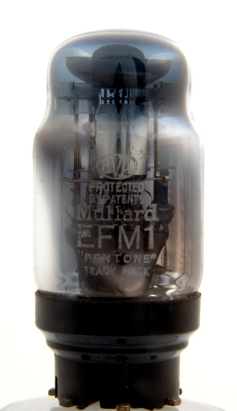
However, the idea of using the screen grid of a signal amplifier valve to amplify the AVC bias lived on for a couple of years in a strange valve, Type EFM1, introduced by Philips-Mullard. This valve had a magic eye section set in the end of an otherwise conventional pentode amplifier, with the control electrode of the magic eye internally connected to g2 of the pentode. Since the magic eye is visually important to the frontal appearance of the set this usually meant that one of the set valves had to mounted awkwardly off chassis with flying leads.To this day I do not understand why anyone should think this a good idea. Apparently, most set manufacturers did not understand why, either. The EFM1 made a brief appearance in some Philips sets but these, and the valve itself, are now collectors' items.
|