|
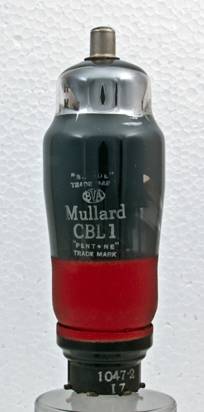
This exhibit has lost most of its identification. What remains is CBL.1.57 which is probably a batch of CBL1's.The CBL1 is a double diode output pentode. The aim of this high mutual conductance valve was to reduce the number of devices in wireless receivers. The CBL1 has a 200 mA heater requirement for heater chain use in receivers without mains transformers. The diodes would demodulate the signal and generate AGC and the resultant audio would drive the output stage directly. This implies strong signals to derive the drive voltage. It is safe to say that this valve was aimed directly at the low cost local station receiver market. The CBL31 was electrically identical but on an IO base. The design probably dates from the mid to late 1930s. The CL4 is virtually the output pentode section of the CBL1 in stand alone form. The EBL1 takes the same high gain idea and translates it for the higher voltages available in receivers with mains transformers.The internal and external coatings together with the silvering from firing the getter all conspire to obscure the electrodes. The cement holding the glass in the base has given way and the valve has been taped up with fabric insulation tape. In the Tungsram CBL1 the manufacturer has placed a shrink wrap sleeve over the valve to keep the two parts together.The cathode resistor is specified as 167 Ohms, the output load as 4,500 Ohms and under these conditions an output of 4 Watts at 10% total distortion is possible.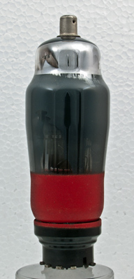
The coating inside the glass prevents a clear view but the diode anodes form a bright box shape below the dark oval anode of the output pentode.The classic envelope is 44 mm in diameter and, excluding the Ct8 base pins, is 128 mm tall.References: Data-sheet & 1043. Type CBL1 was first introduced in 1938. See also 1938 adverts. |
Pin Connections
| 1 | 2 | 3 | 4 | 5 | 6 | 7 | 8 | tc |  m | h | h | k | a(d1) | a(d2) | nc | a | g1 |
|
|
Absolute Maximum Operating Conditions
| Vh | Ah | Va | Vs | Vg | mAa | mAs | ra | gm | 
| 44.0 | 0.2 | 200 | 200 | -8.5 | 45.0 | 6.0 | 35,000 | 8.0 |
|
Updated January 06, 2022.
|
|