The EM84 tuning indicator, or magic eye, was used to display the optimum tuning point of a receiver, or the recording level of a tape recorder. The main benefit in reception was for FM radio where the exact tuning point was harder to determine than for AM. For a tape record level indicator the meeting of the two ends of the column in the centre was set to 100% and overlapping band indicated overload. The total column length change was 21 mm.
Mullard themselves styled the EM84 as a voltage indicator to denote the greater precision of build than was required for the simple task of a tuning indication where only the maxima was important.
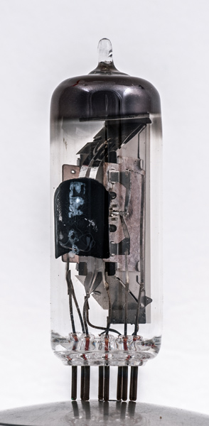
The vertical metal strips on the left are the heater connections to the horizontally mounted triode amplifier. The grid supports can be seen.
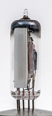
The phosphor strip on the inside of the glass. This example has been used and the phosphor shows some burn. The area that has been burned shows the exact size of the column. In the EM84 the quiescent condition was two green bars, one at each end of the window. As the signal strength increased the bars would elongate and eventually overlap to form a bright green region. The optimum point for tuning was a minimum gap.
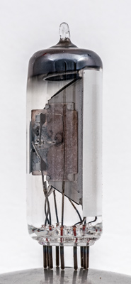
The thin glass tube envelope is 21 mm in diameter and, excluding the B9A base pins, is 61 mm tall.
References: Data-sheet & 1040. Type EM84 was first introduced in 1959. See also1959 adverts.