|
EM85ESensibly equivalent¶ to:See also:
|
|
|
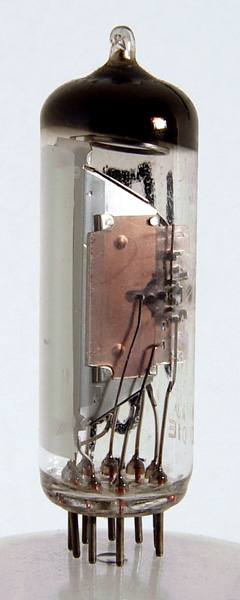
The EM85E tuning indicator uses the closing of two bars to indicate tuning or voltage level. The grid voltage change for full deflection is from -14 to 0 volts. Pin 7 is defined as a deflection electrode and the anode of the indicator is called the target. The grid of the indicator is strapped to the cathode. The first half of the valve is a triode amplifier as is usual.The thin glass tube envelope is 20 mm in diameter and, excluding the B9A base pins, is 62 mm tall.References: Data-sheet & 3002. Type EM85E was first introduced in 1959. See also 1959 adverts. |
Pin Connections
| 1 | 2 | 3 | 4 | 5 | 6 | 7 | 8 | 9 |  g1 | ic | k,g | h | h | t | defl | ic | a |
|
|
Absolute Maximum Operating Conditions
CRT | Vh | Ah | Va | Vg | mAa | 
| 6.3 | 0.21 | 250 | 0/22 | 0.1 |
|
Updated February 20, 2013.
|
|