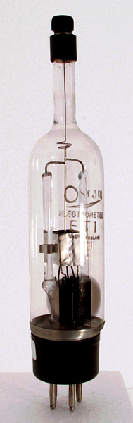
The ET1 is an electrometer valve. The electrometer is an electrostatic instrument. The electrometer valve is a triode with the highest possible input impedance and was designed to have extremely stable characteristics over time and to be isolated from outside influences. The electrometer valves were operated at very low anode voltages, chosen to be well below the ionisation of any residual gas. Additionally they would be operated in the dark to further remove the valve from any source of unwanted electron emission. These extreme precautions enabled the ET1 to be used to measure currents as low as 10-16 Amps. Pin 2 connects to guard rings as well as the screen.
The mutual conductance with the grid at -1.5 Volts and the anode at 2 Volts is 0.04 mA/V. With the anode at 10 Volts and the grid at -1.5 Volts the mutual conductance is 0.16 mA/V. The inter-electrode capacity is 1.6 pF.
Such valves were used in test equipment such as pH meters and photometers.
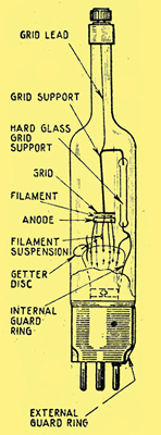
The screw connection and the glass rod supports within the valve to separate the control grid. The image shows the filament between the grid and the anode. This diagram has a single vertical glass support rod whereas the production type has a pair of supports.
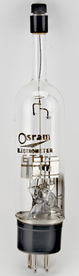
The main image was taken in early 2000. The following images are courtesy of the Lamps & Tubes website.
A general view.
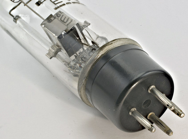
The internal and external guard rings.
The wide glass tube envelope is 36 mm in diameter and, excluding the B4 base pins, is 184 mm tall.
References: Data-sheet & 1043. Type ET1 was first introduced in 1930. See also1930 adverts.