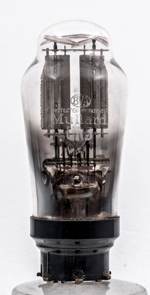
The UR3 is electrically identical to the UR3C that has a B7 base. The ratings are an anode voltage of 250 Volts and a direct current of some 120 mA. The anode is made from mesh - a technique used when occluded gas was a potential problem. The heater is specified at 200 mA - i.e. for series heater chains where equipment could be used on both DC as well as AC mains.
This is one of a small number of types which were intended for use in voltage doubler rectifier circuits (AC only!) in which around 200 VDC could be obtained from 110 VAC mains without using a mains transformer. Alternatively the pair of rectifiers can be run in parallel for greater current output.
Another curious feature is that it has a Philips/European 'U' series type number (where 'U' indicates a 100 mA series-type heater) but its heater current is actually 200 mA! In fact the Philips 'UR' series were ephemeral except for Type UR1C (with B5 base cap) which in redesigned form remained in the lists until the 1960s. The UR1 (with side contact base cap) was also redesigned but was renamed the CY1 in accordance with its heater current rating. The other 'URs' were little used and were obsolete by 1940.
This exhibit has a plain glass bulb with lettering on the side, whereas UR3 has a gold paint disc on the dome that carries the identification.
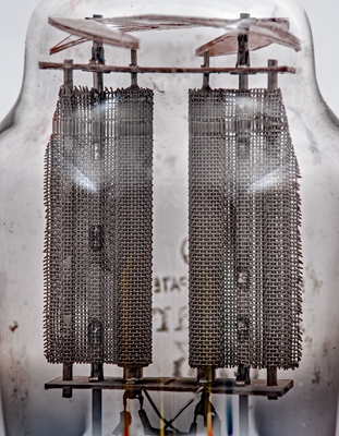
The anodes are wider than the front to back dimension. The extra width is for heat dissipation as the cathode tube sits within a cylindrical space at one end of the mesh.
This image shows how the mesh anode is welded to the central support rod. The cathode tubes are closed to a small diameter at the top and the anode is held at three points in each mica. The mica supports that hold the electrodes firm within the bulb are a separate structure.
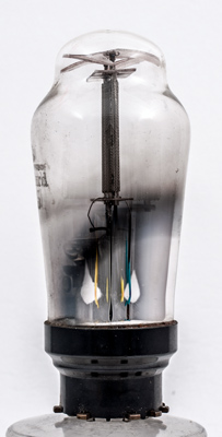
The classic envelope is 41 mm in diameter and, excluding the Ct8 base pins, is 95 mm tall.
References: Private communication, data-sheet & 1043. Type UR3 was first introduced in 1935. See also1935 adverts.