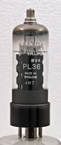
The PL36 was designed as a line timebase output valve for television receivers. The valve was a popular design and made by several companies. We also have a Mullard exhibit of the PL36.
The design dates to the 1950s, when sets were black and white and screen sizes of 14 - 17 inches diagonal was common.
The maximum positive peak voltage on the anode is 7 kV with a 10 W dissipation. The screen dissipation is up to 5 W and the grid is designed to withstand negative peaks of 1000 Volts.
Thanks to Ian Dinnis for donating this NOS valve and box.
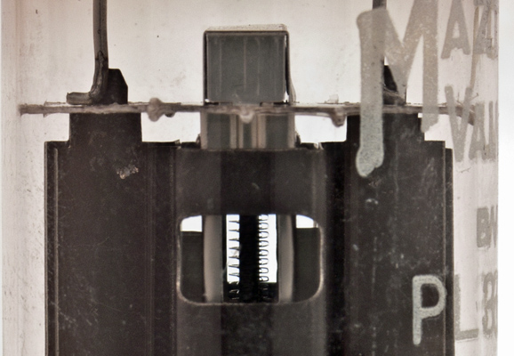
The anode edge on. Through the holes the beam plates and inner grids are visible.
The close-up of the valve shows the internal construction. Very close to the central cathode can be seen the control grid, with the screen grid as the most visible spiral wire. One can see the bright beam forming plates.
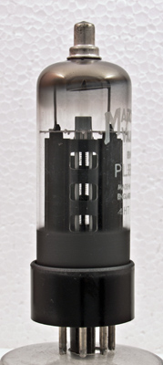
The wide glass tube envelope is 29 mm in diameter and, excluding the IO base pins, is 90 mm tall.
References: Data-sheet, & 1040. Type PL36 was first introduced in 1955. See also1955 adverts.