|
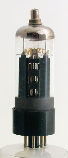
An intact Mazda PL36 from the museum.
In a box of donated valves we found a PL36 that looked as if the vacuum had seen better days. The first suspicion came when the the getter material on the inside of the glass was white rather than silver, the confirmation was made when it was found that most of the envelope was actually missing.
The only reasonable thing to do was to dissect and photograph the process. So here in reverse order is what we saw.
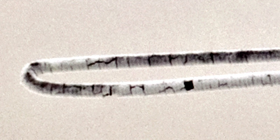
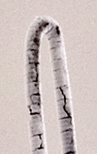
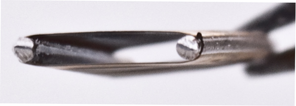
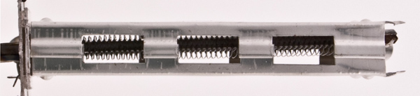
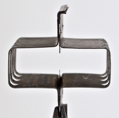
The heater was stuck inside the cathode and in releasing it the coiled heater broke and the coil started to expand. The upper pictures show the hairpin that extended beyond the cathode and through the top mica. Originally the tungsten heater would have been wound on a molybdenum wire mandrel. The latter would have been dissolved away to leave the fine coil of tungsten. This was then coated in ceramic and folded in two before being inserted into the cathode tube. The coated spiral is 0.8 mm in diameter and the heater is wound at 8 turns to the mm.
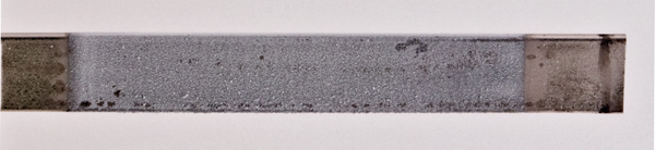
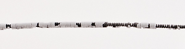
The cathode tube was formed into the rectangular section 4.5 x 1 mm with the sides as flat as possible. The nickel tube was then spray coated with the oxides that would be later decomposed within the envelope while the valve was being pumped to a hard vacuum. Note that the coating is deposited only where the emission is required, along a 25 mm length.
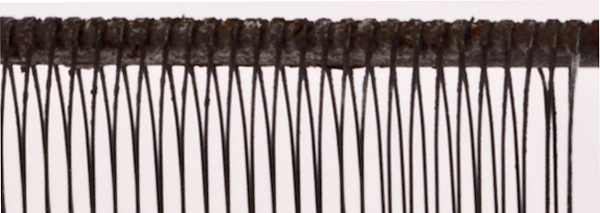
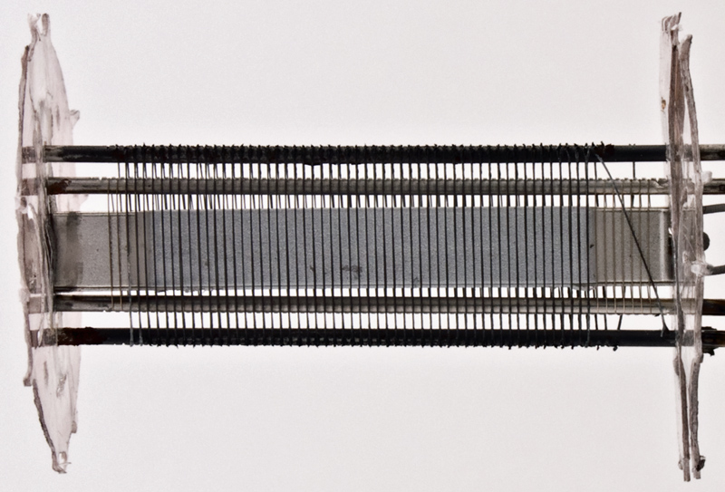
The control grid seen from the end. The wire is firmly held in place in the support rods. The grid winding machine will first cut a notch in the rod, then wind the wire into the notch and finally a roller folds the metal displaced upwards by the notching process back into the notch to retain the wire. This process was known as peening. It can be seen that the wire is not drawn flat across the space between the rods but is slightly bowed outwards. The spacing between sides is 1.5 mm.
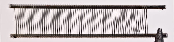
The control grid from the side and face on, the width is 8 mm and is wound to a pitch of 0.5 mm. The grid wire and supports are bright and show no corrosion, unlike the screen grid.
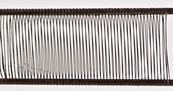
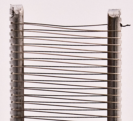
The screen grid from the side. The wire was broken before the dissection process, but here it can be seen how thin the material is. Both grids were probably wound from molybdenum wire as this metal has a low tendency to emit secondary electrons when operating. The grid wire was powdery as if corroded.
The screen grid here seen end on. The gap is 2 mm and the support rods are 11 mm apart. The winding has a pitch of 0.5 mm and extends 27 mm along the rods. In the image below the two grids can be seen to align across the face of the cathode. This is an essential part of the design as by aligning the grids beams (or sheets) of electrons form between the wires and few electrons are caught by the screen grid, thus reducing screen current and hence dissipation.
The two grids are held in place by the top and bottom micas. The cathode tube is not held in the top mica and so is out of alignment. The rigid holding of grids between punched mica sheets was a technological advance that greatly reduced the microphonic effects so prevalent in early valves. Additionally the mica supports were an interference fit within the glass bulb which further added to the stability of the electrode assembly without the need for internal bracing between top and bottom mica sheets. The glass was a 'free' vertical support.
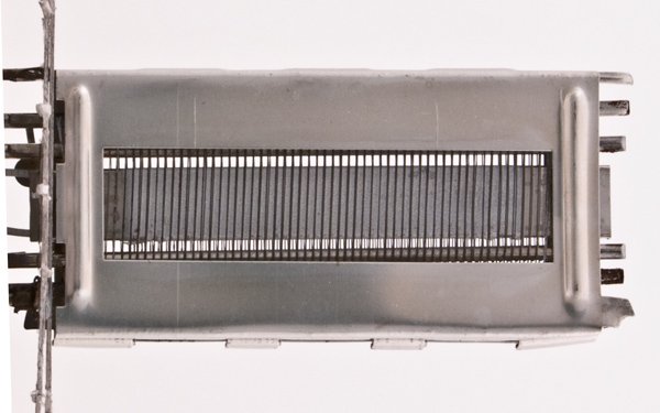
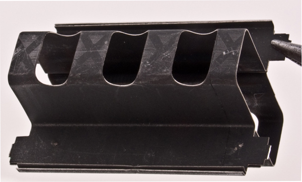
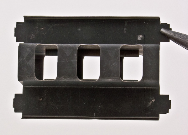
After the heater, cathode, control grid and screen grid are mounted concentrically by the operator in the assembly jig, the beam plates or beam confining plates were added. This is a thin sheet of bright nickel punched with side holes for assisting with cooling and the flat rectangle that defined where the electrons would emerge from between the grids and commence their journey to the anode. In other directions the electrons would be repelled by the cathode potential on the beam plates. The plates are 34 mm long. the rectangle is 16 x 5 mm. The openings in the plate faces are 28 x 7 mm.
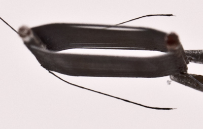
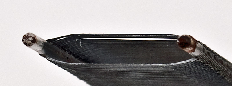
The anode seen end on in both images. It has been formed from two sheets of nickel and has a central spur into the cavity space.
The anode is 30 mm long. Across the flanges is 23 mm. The rectangular opening is 20 x 8 mm. The outer & inner surfaces of the anode are blackened to form a better radiating surface. A black body is the most efficient radiator and it is a surprise to find that the inner surface is not left bright as the last thing the inner structure needs is head radiated back onto it from the anode. The lower picture shows the plate that projects into the space between the anode and the beam plates. This last plate is bright not blackened and leaves a 5 mm gap between the sides.
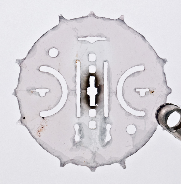
One of two top mica sheets. The centre is blackened by the heat of operation. The very centre slot has side notches to hold the heater, The two slits above and below the centre hold the cathode and along the centre axis are the four round holes that support the grids. On the right further out is a vertical slot for the beam plates. The left side has a pair of horizontal shaped slits for the same purpose. Within each of the semi-circular slots is a hole with a slot. This is where the two sides of the anode are held and additionally a cross piece is fixed outside the mica to hold it firmly in place. One side of the mica rests on the anode and the other side is retained by this small piece of wire. This is more clearly seen in the next image.
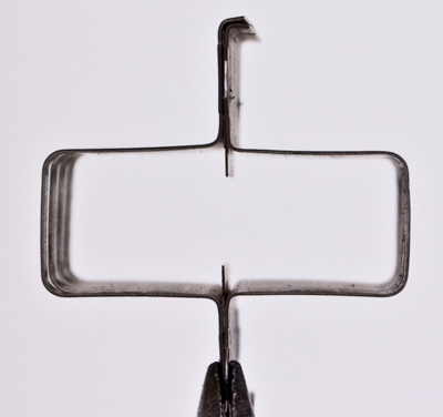
The two anode support rods extend upwards and are welded in the middle to the wire that passes through the top of the envelope and connects to the top cap. Also fixed to the anode supports is the getter holder ring.
Finally after all of these hand assembly operations the main electrodes are spot welded to the wires that have been fused into the base. This was carried out in yet another jig. In total a large number of components are made and assembled before the valve mechanism is sealed into its glass envelope. In this final picture we see the completed valve before being encapsulated.
|