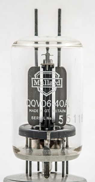
The QQV06-40A is an excellent example of good design. Within the envelope are two beam tetrodes with a maximum anode dissipation of 40 W.
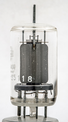
Following the European pattern, a central flat cathode is surrounded by a split control grid (one half per valve), a common screen grid is wound next. The two beam forming plates can be seen either side of the central assembly. The anodes are finned for good heat dissipation and clearly separated from the central structures, the anodes are brought out to pin like top caps.
The heater is centre tapped to allow for 12.6 or 6.3 volt operation.
In use the designer would take care to keep the grid circuitry below the chassis with the anodes being connected to circuits remote from the input. This way undesirable feedback could be avoided.
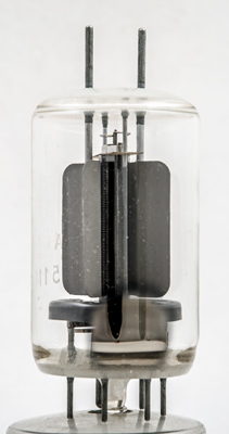
The European design of internal capacitors for neutralisation can be seen at the top of the valve. Such neutralisation prevented parasitic oscillations during operation in a well designed layout.
Each of the two anodes is shaped and supported from the top of the envelope. The top and bottom glass discs are sintered for strength.
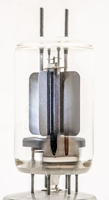
The central tower has the common screen grid as well as the heater and cathode. The control grids are single sided. The grids are wound normally and then sheared at the sides of the supports. The individual wires are held in the notches made during winding.
Some enhancement to show the grid wires. Note also the wires at the top, these form the internal neutralising capacitors.
The wide glass tube envelope is 44 mm in diameter and, excluding the B7A base pins, is 72 mm tall.