|
The number of valves increases steadily each year and the amount of information required about each specimen increases also, for the ever widening variety of uses to which they are put demands a greater knowledge of the characteristics of each type.
A few years ago, with but few exceptions, valves had either 2 Volt or 4 Volt filaments. Now there is a surprising variety. Battery types are still rated at 2 Volts, naturally enough, since most people use an accumulator, and a single cell only is convenient. The indirectly heated types, however, require 4, 6.3, 13, 20, 25, 30, 35, and 40 Volts. The extension of voltages has been brought about by the car set and the AC/DC receiver. In the latter all valves must consume the same current, for they are connected in series; the voltages of the heaters consequently vary in the different types just as the currents taken by the heaters vary in constant voltage valves. The 13 Volt range, which overlaps greatly with the AC/DC range, has been brought into being for car radio, and the valves are intended for operation from the usual 12 Volt accumulator. The 6.3 Volt range has also been developed for the same purpose, but for cars which have only a 6 Volt accumulator.
In America, few, if any, cars have a 12 Volt battery, and so the valves are of the 6.3 Volt type. Although originally developed for car radio and AC/DC sets, they are now almost universally employed in AC receivers, and the older 2.5 Volt types, although still widely used, have been superseded in the newer receivers.
Frequency-changers

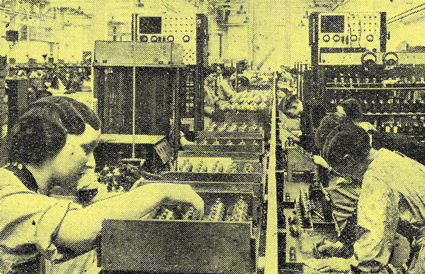
Two special machines in the valve-making department of the Ferranti radio works that are used for the standard routine testing of valve characteristics.
In this fall those valves which have been developed to perform this essential function to the superheterodyne. There are four types:b
- the heptode
- the octode
- the triode-pentode
- the triode-hexode.
The valves perform two functions and consist really of two more or less independent sections. Each contains in essentials a triode oscillator and a multi-electrode mixer.
In the case of the heptode, the cathode is surrounded by two grids which form the grid and anode of a conventional triode oscillator. This assembly is surrounded by a screen-grid, and then comes the control grid of a screen-grid type valve, followed by another screen grid and an anode. This type of valve is thus analogous to a triode oscillator and a screen-grid valve-in series. The octode is similar, but has a suppressor grid between the outer screen-grid and the anode, and is analogous to a triode and an RF pentode in series.
The triode-pentode is quite different, for the two electrode assemblies are entirely distinct save that they operate on a common cathode. No internal interconnection exists and the valve is exactly equivalent to the two-valve frequency-changer built up of an RF pentode mixer and a triode oscillator. External coupling between the two sections must be provided.
The triode-hexode is, relatively speaking, a newcomer. It contains two separate electrode assemblies with a common cathode. One is a triode and functions as an oscillator, while the other is a hexode which serves as a mixing valve. In the construction the cathode is surrounded by the control grid, and this in turn by two concentric screen-grids between which is the injector grid which is internally connected to the grid of the triode assembly. The anode comes outside the outer screen grid.
Apart from the ordinary frequency-changers, one unusual valve will be found among the American types. This is the 6L7, it contains only the electrodes of a mixing valve and requires a separate oscillator. The electrode arrangement is similar to that of a hexode, but there is an extra grid between the outer screen-grid and the anode which functions as a suppressor-grid.
In general characteristics the heptode and octode are very similar, but the latter generally has a higher AC resistance and so damps the first IF tuned circuit to a lower degree. The triode-pentode also has a high AC resistance and generally a high conversion conductance, but has the disadvantage of requiring external oscillator coupling. The triode-hexode has a high AC resistance and a conversion conductance comparable with that of other types, internal coupling is obtained by electronic means and the mutual conductance of the oscillator section of the valve is higher than is generally found with heptodes and octodes. Consequently, it oscillates more readily and can be used at shorter wavelengths. There is also greater freedom from interaction between the signal and oscillator-frequency circuits with this valve, and this is particularly valuable in short and ultra-short-wave reception.
Screen-grid Valves
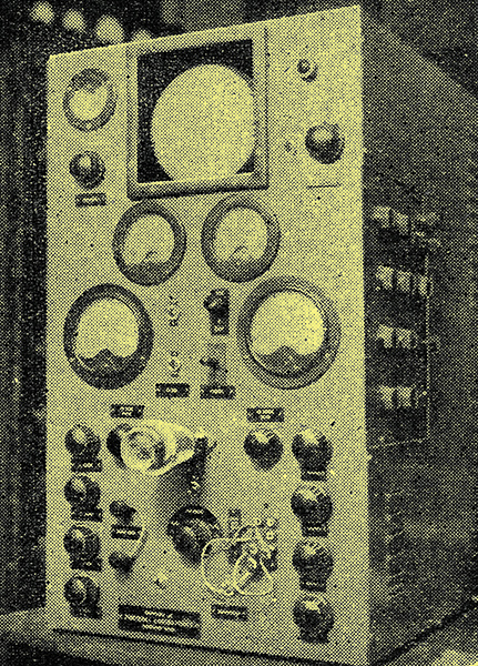
Cathode-ray tube and its associated apparatus used by the High Vacuum Valve Co for the visual examination of the characteristic curves of Hivac valves under working conditions.
The ordinary screen-grid tetrodes and pentodes are now rarely used for RF and IF amplification, having been superseded by the variable-μ types. There are signs, however, of a revival of interest in this class for television purposes. Several makers have recently produced pentodes with very high values of mutual conductance in order to permit reasonable stage gain with the enormous band-width required in a television amplifier. The tetrodes also find application as dynatron oscillators and in the separation of the synchronising impulses in television receivers. This class thus cannot be considered as even approaching obsolescence.
When used as an amplifier the stage gain can readily be calculated by multiplying the mutual conductance of the valve (mA/V) by the parallel value of the dynamic resistance of the tuned circuit and the valve's own AC resistance and dividing by 1,000. When the valve resistance is very high compared with the dynamic resistance, the gain is nearly equal to the product of mutual conductance and dynamic resistance divided by 1,000. Expressed algebraically,
Gain = gRaRD / (Ra + RD) ≈ g when Ra ≫ RD
This same equation is accurate also for other valves. In the case of frequency-changers, conversion conductance must be substituted for mutual conductance, and with resistance-coupled amplifiers RD becomes the value of the coupling resistance in parallel with the grid leak of the following valve. The equation is exact for all classes of amplifiers in which resistance or a resonant tuned-circuit coupling is used. It does not apply when the coupling is largely reactive.
In the past, it has been customary to use the simplified equation (for R, RD) for all calculations with tetrodes and pentodes and to retain the exact expression only for triodes. This is not always justifiable, however, for recent advances in coil design have made possible high values of dynamic resistance, and the simpler equation may lead one seriously astray when dealing with tetrodes and frequency-changers, although it is still reasonably accurate in most cases with pentodes, on account of their higher resistance.
Variable-μ Valves
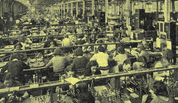
The valve assembly department of the Edison Swan Electric Brimsdown works, where Mazda types are made.
In broadcast receivers the variable-μ valve is now almost universally employed for RF and IF amplification. The stage gain is calculated in the same way as with screen-grid valves of the sharp cut-off type. The difference between the ordinary screen-grid and the variable-μ valve, in fact, is merely that with the former the mutual conductance tends to remain constant as the grid bias is increased and then rapidly falls to zero, whereas with the variable-μ valve the mutual conductance falls continuously and gradually as the bias is applied. In practice, of course, the mutual conductance with both types falls on increasing the bias, but the change is much more gradual and a much higher bias voltage is needed to obtain the same minimum value with the variable-mu valve.
The practical result is that it is possible to control the amplification within wide limits by varying the grid bias of variable-μ valves without distortion or cross modulation being introduced. This statement must be taken conservatively, of course, for there is naturally a limit to the conditions under which freedom from distortion occurs, and even with variable-μ types trouble will be experienced it the input exceeds a certain figure.
With all valves the inter-electrode capacities are important, but they are especially so in the case of types which are used for RF and IF amplifiers. The input and output capacities usually occur in parallel with the tuned circuits and are only important in that they increase the minimum capacity of these circuits and so restrict the tuning range. The effect is most noticeable in short-wave reception, but it must be remembered that a receiver will require retrimming if a valve is replaced by one having different capacities.
The grid-anode capacity, however, is important in that it very greatly affects the stability; it does, intact, place a definite limit to the possible stable gain even with all other couplings eliminated. With a single stage of amplification having identical grid and anode circuits, the limit of amplification is A = 2/ωCga RD when the valve resistance is high compared with the dynamic resistance. With two stages the number 2 in the above equation should be replaced by 1, with three stages by 0.76, and with four stages by 0.67. With RD in Ohms and Ca in micro-Farads, ω = 6.28 times frequency in MHz.
Diode valves are used chiefly as detectors and for AVC purposes. The majority contain two anodes and a common cathode and can provide detection and delayed AVC. In general, they can be safely operated at a much larger signal input than the diodes fitted to the multiple diode class of valve and they often have a lower resistance.
Multiple Diode Types
Valves of this nature are very widely used, and in general one diode acts as a detector while the other provides delayed AVC. In the case of a duo-diode-triode the triode section generally functions as an AF amplifier, but with a duo-diode RF pentode the pentode section is normally the last IF amplifier. These valves also find application in amplified AVC circuits.
Triodes
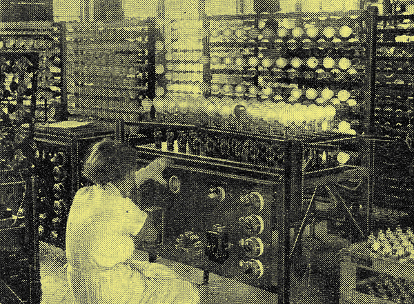
Brimar valves being subjected to the ageing test in the Standard Telephones and Cables factory at Footscray, Kent.
Triodes are divided into two categories: those with a resistance greater than 7,000 Ω and those with a resistance less than 7,000 Ω. The former are now used chiefly as AF amplifiers, grid detectors, and oscillators, while the latter are output or driver valves.
For a grid detector or AF amplifier a valve with a resistance of 7,000 - 10,000 Ω is usually the best from the point of view of quality, but where high amplification is important a higher resistance can be selected. The deterioration in quality will usually be small and in some cases non-existent, depending very largely upon the circuit conditions. In calculating the amplification from the formula already given it is important to remember that the mutual conductance and AC resistance both depend on the operating voltages. Following the standard practice the actual values at maximum HT and the optimum negative grid bias are not widely different, but when using resistance coupling it is a wise plan to take the resistance as being about 25% greater than the figure given and the mutual conductance as about 25% less.== Valves having resistances below 7,000 Ω are chiefly of the output type and the power output obtainable is undoubtedly the most important characteristic. Unless an adequate output is obtained it is impossible to secure good quality reproduction. The output necessary depends on the loud speaker efficiency and on the volume required. Experience shows that 2,000 mW are needed for ordinary room strength, but that where the very best quality is desired, and particularly when the high and low frequency responses are unusually well maintained, some 4,000 mW should be allowed.
The output figures are obtained only when the valve is operated into the correct load impedance. The speech coil of the loud speaker rarely has the correct impedance so that an output transformer is necessary, and the ratio is readily calculated by dividing the optimum load impedance by the speech-coil impedance and taking the square root of the result. When the speech-coil impedance is less than the optimum load impedance, the transformer ratio is step-down.
Tetrodes and Output Pentodes

Final testing of Brimar valves by taking meter readings of their characteristics.
The pentode as an output valve has the advantages of higher sensitivity and efficiency. It is more sensitive in the sense that it requires a smaller signal voltage on the grid for the same power output, and it is more efficient in the sense that it will give the same power output with a smaller consumption of power from the HT supply. In some cases, however, these advantages are more than offset by the high AC resistance of the valve, which leaves the loud speaker un-damped, by the necessity for accurate matching of valve and loud speaker, and by the comparatively large amount of third harmonic distortion introduced.
The result is that from the point of view of quality the triode is to be preferred, especially if two can be used in push-pull. Good results can be secured from pentodes, however, particularly if the sacrifice in sensitivity involved in the application of negative feed-back can be tolerated. It should be noted that the optimum load impedance for a pair of pentodes in push-pull is not twice the value for one valve, as it usually is with triodes. The optimum load for two valves is of the same order as that for one, because second harmonics are largely balanced out by the push-pull connection, whereas third harmonics are not, and both are present to an appreciable extent with pentodes.
The tetrodes included in this section are of several different types. There is first the Harries Output Tetrode A15 (Hivac) in which the negative-resistance kink in the characteristics of the conventional tetrode has been eliminated by critically spacing the anode from the other electrodes instead of by introducing a suppressor-grid. It is claimed that this results in an improved performance.
The second output tetrode is American, the 6L6 Beam Power Tube, and is in some ways rather similar. It is a large output valve and is really intended for use in push-pull, since rather a large amount of second harmonic distortion occurs with only a single valve. The best results are secured with two in push-pull and with negative feed-back.
Quiescent Output Valves
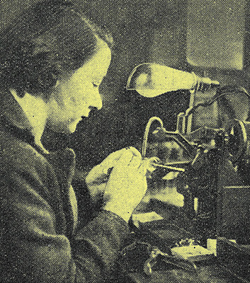
An electric spot welder being used during the assembly of Hivac valves.
The Class B valve consists of two triodes mounted in a single glass envelope and operated in push-pull. Zero, or only a small negative bias, is used, with the result that grid current flows during a large part of the cycle of input voltage.
The valve characteristics are similar to those of pentodes, so that careful y match to the loudspeaker is necessary. It is especially important that the output transformer should have a low DC resistance and that the leakage should be small. The valve has a low input impedance and requires a power rather than a voltage input. It must be fed from a push-pull transformer having a secondary of low DC resistance and the preceding or driver valve must be capable of an adequate power output. The driver transformer usually has a step down ratio which can be calculated by dividing the optimum load of the driver valve by the input impedance of the Class B valve and taking the square root of the result.
Class B stages have now been largely superseded by QPP so far as battery sets are concerned. The QPP valve is really a double pentode and at large grid bias is used so that the standing anode current is very small. Grid current does not flow, so that no difficulties arise in the input circuit as they do with the Class B stage. The output circuit is treated exactly as any other.
Among the American valves will be found many indirectly heated Class B types. These are intended primarily for considerable output in mains-driven equipment, but they are often operated as amplifiers under Class A conditions. A single valve will then operate as a complete push-pull stage giving a compact and economical assembly.
Rectifiers
Ferranti valves after construction are carried in trays on a conveyor belt to the site of each testing operation.
Few remarks are necessary on rectifiers, but it is as well to, point out that for output assume a 4 μF reservoir capacitor. This capacitor must be rated for working at not less than 1.4 times the. RMS AC input to the rectifier. Thus, the reservoir capacitor used for a full-wave rectifier with an input of 500-0-500 Volts must be rated for working at not less than 700 Volts.
There are two general types of rectifier directly heated and indirectly heated. With the former, the valve functions a few seconds after the set is switched on, so that if the receiving valves are indirectly heated most of the capacitors connected, even remotely, to the HT line are charged nearly to the peak value of the AC supply to the rectifier. Consequently, to avoid breakdown, all capacitors should have the same voltage rating as the reservoir capacitor.
This is avoided with. the indirectly heated type, however, for the rectifier does not become operative until the other valves have warmed up and are ready to draw current. Capacitors thus need be rated only for the normal working voltages. Care must be taken, however, to choose a rectifier which takes at least as long to become operative as the other valves. If the rectifier cools more slowly than the other valves, there is a risk of a breakdown if the set is switched on within two or three minutes of being switched off, for then being hotter than the other valves to start with, it is operative quicker.
Opinions are divided on the relative merits of the two types. In any case, it is a wise plan to use directly heated valves in the output stage, for then there is always a considerable load on the mains equipment and the possible voltage rise is severely limited.
A number of new rectifiers rated for very high voltages is to be found. These are of the half-wave type and are intended for providing the very small current taken by a cathode-ray tube. They are primarily television valves. The reservoir capacitor with these is usually 0.1 μF.
|