|
The negative feedback principle is one of the most important of recent developments and its principles and applications are discussed in some detail in this article. It is in the output stage of AC/DC equipment that it seems likely to prove of greatest advantage, and an amplifier employing these principles can be found here.
The attainment of a high standard of reproduction is by no means difficult in the case of equipment designed for operation from the AC supply mains, for it is easy to secure ample power in suitable form for the valves. The DC mains user, however, has hitherto been at a serious disadvantage for, although he can obtain plenty of power economically, it is at too low a voltage for the best use to be made of it. As a result, he has had to tolerate a considerably greater amount of amplitude distortion than his brethren having AC supplies need do.
This has now been changed, and the development of the negative feed-back principle has made it economically possible to build a DC mains amplifier which is strictly comparable from the point of view of quality with the best AC apparatus. The principle is not, of course, confined to DC sets, and should lead to a considerable improvement when applied to battery operated equipment. Its advantages will also manifest themselves when it is used in AC equipment of the same type. They are, however, less important in this case, for there is no necessity to use this same type of equipment, and the high standard of quality required may be, and often is, obtained by other methods which are inapplicable to DC and battery apparatus.
The negative feed-back principle is by no means new, being developed by Black some years ago [★] Stabilised Feed-back Amplifiers, by H S Black. Bell System Technical Journal, Jan., 1934, and Electrical Engineering, Jan., 1934., and has been used in communication work both in this country and in America; it is, however, only just finding application in broadcast reception. As applied to any individual stage of an amplifier, it means that a portion of the output voltage is fed back to the input so that it opposes the input voltage. The amplification of the stage is consequently reduced, but so are both amplitude and frequency distortion. Moreover, the effective output impedance is altered, and the input impedance may be also.
The Output Stage
Before the advantages of negative feedback can be appreciated it is necessary to be familiar with the characteristics of existing amplifiers. The greater part of the distortion in well-designed equipment occurs in the output stage, and it is certainly this stage, more than any other, which worries the designer of DC and battery equipment. There are two general types of valves which can be used, the triode and the pentode.
The triode has characteristics such that the amplitude distortion which it introduces consists chiefly of second harmonics. These can be balanced out by the use of two valves in push-pull, and an output stage causing an extremely small degree of amplitude distortion can readily be obtained. Furthermore, the valves require a load resistance which is high compared with their own internal AC resistance, with the result that the dynamic valve characteristics are much straighter than the static. As a corollary of this, the loud speaker is heavily damped by the valve resistance, for in effect the AC resistance of the valves is connected across the output transformer primary, and is much lower than the impedance which the transformer presents to the valves.
A valve having an AC resistance of 1,000 Ω, for instance, usually requires a load impedance of some 4,000 Ω, and the transformer ratio is chosen to give this load. Looking backwards from the loud speaker, however, the speech coil is effectively shunted by one-quarter its own impedance (the valve resistance divided by the square of the transformer ratio), and is consequently heavily damped. The importance of this is evident when it is remembered that damping the loud speaker reduces the effect of resonances in the speaker at low audio frequencies. In spite of its good characteristics from a distortion viewpoint the triode suffers from three disadvantages. Its sensitivity is low, that is, it requires a large signal input for its output; its grid bias is often as high as 12-25% of its anode voltage; its efficiency is fairly low, that is, only some 20-25% of the DC anode power can be converted into useful AC power for operating the loud speaker.
Now the pentode has the advantage of high sensitivity, a comparatively low grid bias and higher efficiency, and it is because of these advantages that it is so widely used. Its characteristics are not nearly as straight as those of a triode, however, and as the load impedance must be much less than its AC resistance, it exercises a negligible straightening effect on the characteristics. Because of this low load impedance, the valve does not damp the loud speaker appreciably, and speaker resonances are not reduced.
Moreover the shape the characteristics is such that both odd and even harmonics are produced, and in consequence the use of push-pull is not of great advantage, while the magnitude of load impedance becomes quite critical.
In spite of its disadvantages, the pentode is widely used because of its high sensitivity, which often permits the saving of one AF stage. In the case of DC sets, however, there is little alternative because its low value of grid bias enables a higher anode voltage to be obtained, and consequently a greater output. With automatic grid bias, the bias voltage is necessarily subtracted from the HT supply the available anode voltage being equal to the HT voltage less the grid bias. With DC mains the HT supply is limited, and must be less than the mains voltage by the drop in the smoothing equipment. After smoothing, there is often less than 180 Volts available for the receiver.
It is easy to see that it out of this 180 Volts some 20-30 Volts must be used for grid bias, we shall be able to supply the output valve with perhaps 150-160 Volts only for its anode. A pentode, however, needs only about 7 Volts bias, with the result that an anode voltage of some 173 Volts may be obtained. This increased anode voltage coupled with the somewhat greater efficiency of the pentode enables an appreciably greater output to be obtained.
It is clear that the main disadvantages of the pentode are the high harmonic content of the output and the high output impedance of the valve. If these can be overcome, then it will not suffer in at comparison with a triode, and may even have advantages over it. The use of negative feedback enables some or all of the defects to be overcome, and thus it is a real contribution towards better quality.
Feedback by Cathode Resistance
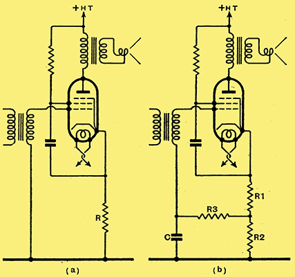
Fig. 1. - Negative feed-back is most readily applied by omitting the usual by-pass capacitor across the bias-resistance R as shown at (a). A greater amount of feed-back can be secured by adopting the connections of (b).
There are several ways of obtaining negative feed-back, but they do not all offer the same advantages. It is, therefore, necessary to consider them in some detail. One of the simplest arrangements is shown in Fig. 1 (a), and will be seen to consist merely of the omission of the usual bias resistance bypass capacitor. The resistance R is the bias resistance, and since the AC component of the anode current flows through it, AC voltages are developed across it. The input voltage of the stage is that which appears across the secondary of the input transformer, but this is not, as is usually the case, the voltage effective in operating the valve. This last is the voltage between grid and cathode, and is equal to the input voltage less the voltage across R.
If R were perfectly by-passed so that no feedback took place, the voltage amplification between the input transformer secondary and the output transformer primary would be μRL / (Ra + RL), where μ and Ra are the amplification factor and AC resistance respectively of the valve and RL is the load impedance presented by the transformer. For simplicity this is assumed to be a resistance. When the bypass capacitor is omitted, as in Fig. 1(a) the gain becomes μRL/(Ra + RL + R(1 + μ)). The gain is reduced in the same proportion as if the valve resistance were increased from Ra to Ra + R(1 + μ).
We have seen, however, that a high valve resistance is undesirable, and that the normal resistance of a pentode is too high. It would seem, therefore, that this circuit is undesirable, since it appears to increase rather than reduce the AC resistance. We must be careful in defining the AC resistance, however, for what we really want to know is the apparent output resistance Ro which would be measured between the output terminals when the output transformer is disconnected. This is the; resistance which is effective in damping the loud speaker.
Assuming the grid to be shorted to the cathode, the value of Ro would obviously be R + Ra, but with the connections of Fig. 1(a) it is different because a change of anode current alters the grid voltage which in tum reacts on the anode current. Suppose we increase the anode voltage slightly, what happens? Obviously there is first of all an increase of anode current, and consequently a greater voltage across R. The cathode however, becomes more positive than before with respect to the earth line, and hence the grid, so that the grid becomes more negative with respect to the cathode. This change in grid potential tends to reduce the anode current and so offset the original increase. The change in anode current for a given change in anode voltage is thus less than it would be if feedback were absent, and the effective output resistance is higher. Actually Ro = Ra + R(1 + μ).
This circuit is consequently of use only when the high value of Ro is not objectionable. The amount of feedback is controlled by the value of R, but as this must be fixed by the grid bias needed some modification is often required. When R must be less than the value needed to provide bias, it can be made up to the required total by an additional series resistance which can be shunted by a large capacity capacitor. When the bias resistance is not large enough, however, the arrangement of Fig. 1(b) can be adopted. Here C and R3 can be assigned arbitrary values of some 2 μF. and 50,000 Ω while in the equations R = R1 + R2. Only R1 is effective for producing grid bias, however.
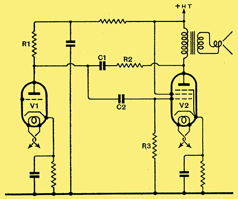
Fig. 2. - A feed-back circuit which has the advantage of greatly reducing the apparent AC resistance of the output valve. As explained in the text, this circuit is unsuitable for general use.
Another scheme which at first seems particularly attractive is shown in Fig. 2. The circuit is that of a normal resistance coupled stage except for the addition of C1 and R2. Actually C1 plays no part in the operation save that of insulating two points of different DC potential. It must however, be large enough for its reactance to be negligible compared with the resistance of R2 at the lowest frequency required.
Circuit of Low Output Resistance
Actually, this resistance R2 forms a potentiometer across the output with the resistance of V1, R1, and R3 all in parallel. The proportion of the voltage developed across the output transformer which is fed back to the grid is R / (R + R2) where R is the combined value of the resistances enumerated above. It is also easy to see that a rise in anode voltage causes a positive change in grid potential with the result that the effective AC resistance of the valve is lower than its normal value.
A rise in anode voltage is a normal accompaniment of an initial grid voltage change in a negative direction, so that the feedback is in the correct phase to oppose any voltage change applied to the grid, and to assist any voltage change due to the injection of voltage in the anode circuit. As a result, we can have the combination of negative feedback with a low output resistance, which is just what we require.
Unfortunately, the circuit has one disadvantage, and it is one which is serious enough to prevent its use in practice. It is clear that as the anode and grid of the two valves are joined together through a capacitor, they must be always at the same AC potential. Now the feedback necessarily reduces the voltage changes on the grid of the output valve, and, consequently, it is clear that with this circuit it will also reduce the voltage changes on the anode of the preceding valve. This is equivalent to reducing the anode circuit load impedance of V1, and, in consequence, this valve may easily be overloaded.
Owing to this fault, the circuit is not one which can be recommended, and there would be no useful purpose in giving the design equations. It is sufficient to say that with the degree, of feedback necessary to give an output resistance of 1,000 Ω with a pentode and a distortion reduction to about one-fifth, the effective input resistance of the pentode is about 2,500 Ω only. The preceding valve can only give an undistorted output if it has a load resistance of at least 30,000 Ω it cannot amplify without distortion if it has to work into a load of 2,000-3,000 Ω only.
A Practical System
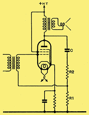
Fig. 3. - A practical circuit giving all the advantages of negative feed-back and a low output impedance.
A little thought soon shows the reason for the defects of the two arrangements which we have considered. The system of Fig. 1 has an infinite input impedance, or rather the normal input impedance of an amplifying stage, because the signal and feedback voltages are introduced in series into the grid circuit, but it has a high output impedance because the valve and source of feedback voltages are in series across the output transformer. Now with Fig. 2, the low input resistance is due to the signal and feedback voltages being in parallel, while the low output resistance is due to the valve and source of feedback voltages being in parallel.
It is thus clear that for the desired conditions of high input and low output resistance we must adopt the series input teed of the first circuit with the parallel output of the second. This can be done if we adopt transformer coupling to the output valve, and the circuit of Fig. 3 is free from the limitations of the earlier ones. The input resistance is that measured between the secondary terminals of the input transformer, and is obviously no different from that of any ordinary valve. For most purposes we can call it infinite.
The output impedance is the same as that of Fig. 2, when the resistances have appropriate values. Actually,
Ro = Ra/(1 + (Ra + μR1)/(R1 + R2)).
The stage gain from the input transformer secondary to the output transformer primary is given by
A = gR″ / (1 + gR″ R1 / (R1 + R2))
where g is the mutual conductance of the valve (A/V) and
R″ = R′ (R1 + R2)/(R′ + R1 + R2)
and
R′ = RaL/(Ra + RL)
In design, we require most generally to start off by reducing the output resistance to a known level. The equation for output resistance is consequently best written in the form
R2 = R1 ((1 + μ + Ra/R1 - Ra/Ro) / (Ra/Ro - 1)).
In addition R1 + R2 must be much larger in value than RLL, otherwise some of the power output of the valve will be wasted in these resistances. The values of these resistances must not higher than necessary, however, otherwise stray capacities will upset the performance at high audio frequencies.
Let us as an example take a concrete case of a Mazda Pen3520 valve. Under average conditions we may expect anode and scree voltages of about 185 Volts and the valve then requires a grid bias of 7.25 Volts. The optimum load resistance is 4,400 Ω, and the normal output 2.45 Watts for 4.5% second harmonic and 4% third harmonic distortion. The input is 5.8 Volts peak, and the valve curves show Ra be approximately 89,000 Ω with g = 7.25 mA/V and μ = 650.
In order to find R2 We have to decide on Ro and fix an arbitrary value for R1. We know from experience with triodes that a valve resistance of 1,000 Ω damps the loud speaker satisfactorily, so let us say Ro = 1,000 Ω and try R1 = 5,000 &Omega. We then have R2 = 5,000 ((1 + 650 + 17.8 - 89)/(89 - 1)) is 33,000 Ω. The nearest standard value is 30,000 Ω, and this will lead to a somewhat lower value of Ro and make R1 + R = 35,000 Ω, which is eight times the load resistance.
Now as to the stage gain; we have R′ = 4,190 Ω and R″ = 3,740 Ω, so that A = 0.00725 × 3,740/(1 + 0.00725 × 3740 x 5,000 / (5,000 + 30,000)) = 5.56. Normally if feed-back were not used and R1 and R2 were absent the gain would be gR′ = 30.4 times, so that the use of feed-back reduces the gain to 1/5.45 of its normal value. As the valve usually needs an input of 5.8 Volts peak, it will now need 5.8 × 5.45 = 31.6 Volts peak. This is about the value required by an average triode output valve, so that in effect the use of feed-back converts a pentode into a triode, for the stage has the same output impedance and requires the same input voltage.
Now as to distortion. An exact analysis is much more difficult than is the case when dealing merely with amplification, but the general effect is to reduce the distortion in the same ratio as the reduction of amplification. In this case, therefore, where we started with 4.5% second and 4% third harmonic and the reduction of gain is 1 / 5.45, we should expect with feedback to obtain only 0.825% second and 0.735% third harmonic distortion. This is actually a lower distortion level than one would expect from a single triode.
It would seem that from at pentode with negative feedback one can expect somewhat less distortion than with a triode when the conditions are adjusted so that both valves require the same input and give the same output. Both stages will have similar input and output, impedances, but the triode stage will require more HT voltage. With two valves in push-pull, there should be less to choose between the two, and either system should give the same output with equally low distortion and require the same input. Again, however, the triode stage will need about 100 Volts more for the total HT supply.
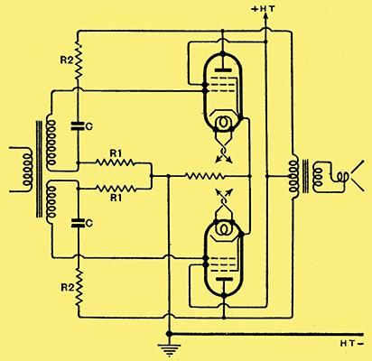
Fig. 4. - The circuit of Fig. 3 applied to a push-pull amplifier necessitates. the use of an input transformer with a split-secondary. It is sometimes necessary to shunt the secondaries with high resistances to maintain an even frequency response.
It is, of course, necessarily to use an input transformer, and with push-pull a split secondary winding must be used as shown in Fig. 4. Practical experience indicates, moreover, that the transformer must have its secondaries shunted by resistances, otherwise a phase-shift occurs at high frequencies which leads to an excessive response around 10,000 Hz. With such a circuit, it should not be difficult to obtain a performance on the limited voltage of DC mains which is truly comparable to that which AC users have long enjoyed from a pair of triodes of the PX4 type, that is, a truly undistorted output of some 3-4 Watts and good damping of the loud speaker.
In conclusion, it may be remarked that negative feed-back also reduces frequency distortion by rendering the gain less dependent on the anode circuit load impedance. It also lends itself to tone-control circuits of simple nature, provided that one does not object to some increase in amplitude distortion of the frequencies which are boosted.
It is clear, however, that the circuit is much less useful with triodes than with pentodes, for the gain of the former is already low, and cannot well be further reduced without leading to difficulties in the penultimate stage. At the present time the chief advantage of the arrangement is to give a pentode a performance which approaches that of a triode as regards quality of reproduction.
|