|
Stability problems in HF and IF amplifiers.
The question of feed-back through the inter-electrode capacity of an HF valve is one of importance even in these days of screen-grid valves. The precise effect of the feed-back upon amplification is dealt with in some detail in this article, and it is shown to he greater with many HF pentodes than with screen-grid valves.
The popularity of the superheterodyne has largely overshadowed the difficulties attendant upon the attainment of a high degree of high-frequency amplification, for in such a receiver it is often split up and obtained at different frequencies. A number of factors have combined to make a fresh study of the conditions governing stability in such amplifiers of considerable practical importance, however, and these are chiefly the tendency towards the use of. higher intermediate frequencies in superheterodynes and the increase in valve capacities which has recently taken place.
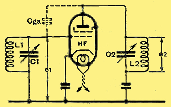
Fig. 1. - The fundamental circuit of an HF amplifier; the grid-anode valve capacity is represented by Cga.
It may be said at once that there is no inherent difference between at high-frequency amplifier and an intermediate frequency amplifier, and the only practical difference is that the former is usually tunable over a band of frequencies whereas the latter is not. The skeleton circuit diagram of a single stage of a typical amplifier is shown in Fig. 1, and the amplification of the stage is defined as the ratio of the voltage e2 appearing across the tuned anode circuit L2C2 to the voltage e1 applied between the grid and cathode of the valve. When the dynamic resistance R of the tuned anode circuit is small compared with the internal AC resistance of the valve, as is usually the case in practice, the stage gain is given by the simple formula e2e1 = gR, in which g is the mutual conductance of the valve in milliamperes per Volt and R is the dynamic resistance in thousands of Ohms.
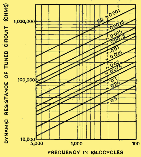
Fig. 2. - These curves enable the maximum permissible dynamic resistance of the tuned circuits to be determined at any frequency for any likely valve. The figures against the curves refer to the-product of mutual conductance (mA/V.) and valve capacity (pF).
This amplification is only obtainable in practice if there is no stray coupling between the input and output circuits of the valve, and even if the screening and decoupling be perfect, this can never be the case on account of the capacity existing between the grid and anode of the valve itself. Early screen-grid valves had a grid-anode capacity of about 0.01 pF but in more recent types the capacity has been brought down to about 0.002 pF. The maximum stable amplification obtainable depends upon the value of this capacity. the mutual conductance of the valve, and the efficiency of the tuned circuits employed in both grid and anode circuits. When both tuned circuits have identical characteristics, the maximum dynamic resistance for various conditions can be determined from Fig. 2. From the point of view of stability, neither mutual conductance nor grid-anode capacity is as important as their product, and accordingly it is this which is shown.
Maximum Dynamic Resistance
A typical modern screen-grid valve has a mutual conductance of 2 mA/V and an inter-electrode capacity of 0.0025 pF, so that under average conditions gC = 0.005. At 110 kHz, therefore, the dynamic resistance must be kept below 780,000Ω, and it is very unlikely ever to exceed this figure in practice. At 1,600 kHz, however, it must be below 200,000Ω. Owing to dielectric losses, it is difficult to obtain a dynamic resistance much above 100,000Ω at this frequency, so that we find that with a typical screen-grid valve instability due to feed-back through the inter-electrode capacity is unlikely with a single-stage amplifier embodying any normal tuned circuits. Where instability is found, therefore, its cause is almost invariably stray external couplings.
It is important to note, however, that the HF pentode is usually considerably inferior to the screen-grid valve from the stability viewpoint, for its grid-anode capacity is often much higher. The writer knows of only one HF pentode which is comparable with the screen-grid valve in this respect, and it is outstanding among its fellows in having a mutual conductance of 2 mA/V with a grid-anode capacity of only 0.0025 pF. In general, an HF pentode has a capacity of ten times this figure, and in one example it is as high as 0.1 pF. This valve has a mutual conductance of 3.4 mA/V, so that gC = 0.34, and even at 110 kHz the dynamic resistance cannot exceed 85,000Ω
The valve capacity increases with mutual conductance, but not proportionately, so that there is an optimum combination for maximum stable amplification. So much depends upon the design of the valve that it is impossible to give any definite ruling, but it may be said the product gC should be as small as possible and g as high as possible.
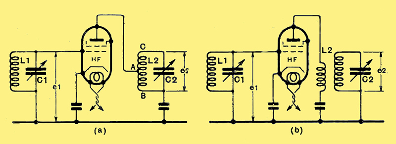
Fig. 3. - A tapped tuned anode coupling is shown at (a) and a transformer at (b).
In many cases, the anode coil is tapped as in Fig. 3 (a) or a transformer is used as in Fig. 3 If we denote the ratio of the turns between AB in (a) to those between BC, or the ratio of the primary turns to the secondary turns in (b), as 1:n, and both tuned circuits have the same dynamic resistance R, then the value of dynamic resistance to be used in the curves of Fig. 2 is not R, but R/n, Thus if we have a value of gc = 0.1 and our tuned circuits have dynamic resistances of 100,000Ω at 1,000 kHz we shall find instability with the circuit of Fig. 1, for R must not exceed 56,000Ω under these conditions. If we use the circuit of Fig. 3, however, and make n = 100,000/56,000 = 1.78, we shall just obtain stability. Actually, of course, we should in practice make the turns ratio at least 1:2 in order to give a factor of safety, since external stray couplings can never be reduced to zero.
In a multi-stage amplifier, of course, great care must be taken to avoid instability, and the permissible dynamic resistance is lower. When two valves are used instability will occur due to the anode-grid valve capacities when the dynamic resistance of the circuits is only one-half of the figure obtainable from Fig. 3; when three stages are used, the resistance must be divided by 2.62, and by 3 when four valves are employed.
Stage Gain
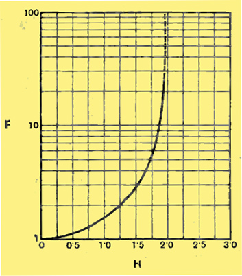
Fig. 4. - With the aid of this curve it is possible to calculate the increase in stage gain due to feed-back.
The feed-back which is always present has the effect of increasing the amplification of the valve, and it is possible to calculate this increase fairly readily. Taking feed-back into account, e2/e1 = gRF; F can be found from the curve of Fig. 4 when H is known, and this symbol can be evaluated from the simple -formula H = gωC R2 in which g = mutual conductance in Amps/Volts, C = grid-anode capacity in Farads, R = dynamic resistance in ohms. Suppose we wish to use a single HF stage in a straight set operating on the medium waveband, and that we have available a valve of mutual conductance 2 mA/V. and with gc = 0.005. The highest frequency to which the receiver must tune is 1,500 kHz, and Fig. 2 shows that stability will be maintained, as far as feedback through the inter-electrode capacity is concerned, if the dynamic resistance is below 208,000Ω. We are unlikely to obtain a resistance greatly exceeding 100,000Ω with average coils, however, so we need not fear trouble from instability on this score. The coils usually have the highest dynamic resistance at 1,000 kHz, and let us assume that at this frequency it reaches 150,000Ω. A glance at Fig. 2 shows that we need fear no trouble from inherent instability with this valve.
The next step is to calculate the amplification which is equal to gRF = 300F. The gain of the valve without reaction is 300 times, and we must evaluate the increase due to the valve capacity. We have:
H = gωCR2 = 2 × 10-3 × 6.28 × 106 × 2.5 × 10-13 × 1.52 x 1010 = 0.708;
from Fig. 4, H = 1.25. so that the true amplification is 300 × 1.25 = 375 times. Small though it is, the grid-anode capacity of 0.0025 pF gives an increase of 25% in the amplification in this case. It must, of course, be remembered that the calculation assumes perfect external screening, and where care is not taken in the design of a receiver, instability might be found which could not be in any way blamed on the valve.
It is interesting to note, however, that, had a valve been selected with a value of gC = 0.025, the stage would be unstable at 1,000 kHz with the particular coil selected, and it would be impossible to stabilise it without decreasing the amplification or neutralising the valve capacity. A value of this order is by no means rare with an HF pentode, and the moral is to exercise considerable caution in the use of such valves at high frequencies. HF pentodes with low grid-anode capacities can be obtained, but if they cannot be employed for any reason, it is safer to employ the screen-grid type of valve, except, perhaps, in the last stage of the amplifier where a large output may be needed for AVC purposes.
The effect of the grid-anode capacity on stability and stage gain has now been discussed in some detail, and it remains to comment on its influence on selectivity. The whole question has been very thoroughly dealt with by M O'Connor Horgan in the September issue of The Wireless Engineer, and those interested in the mathematics of the subject are referred to his paper. It may be said, however, that when an HF amplifier is tuned in the usual way for maximum signal strength, the various circuits are not tuned to resonance with one another if there is any appreciable feed-back. Instead, the circuits are slightly mis-tuned to produce maximum amplification through the aid of the stray regeneration.
Detuning
The effect of feed-back on the selectivity, therefore, is two-fold. First, there is a gain due to the lowering of the circuit losses, and, secondly, there is a loss due to the mis-tuning of the circuits. Almost invariably the gain exceeds the loss, and the chief effect of the mis-tuning is to render the resonance curve asymmetrical. The degree of mis-tuning may be quite large, and in one example the author of the paper referred to quotes a figure of 2 kHz.
It is almost certainly this effect which is responsible for the difficulty in obtaining proper band-pass effects from closely coupled tuned circuits when these are included in an amplifier. It is not difficult to obtain measured response curves almost completely symmetrical with the correct double-hump from a single valve and transformer, but it seems almost impossible to obtain the correct shape of curve when several transformers are used. Invariably, the response curve degenerates into one with a single peak with a small bump in one side! Stray couplings in an HF amplifier, therefore, may exercise a profound effect upon its performance, even if they do not lead to actual instability. The effect of coupling external to the valve is similar to that of the grid-anode capacity, but the latter represents the minimum below which a reduction of feed-back is impossible unless neutralised circuits are adopted.
|