|
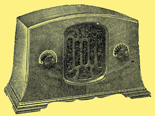
The Midget Superheterodyne - a typical example.
America's most popular set described. The author has just returned from the USA, and has had ample opportunity to study present tendencies in receiver design. Except for shortcomings in its tonal quality, the small and cheap American set was found to be surprisingly effective.
Superheterodynes have virtually replaced straight sets in America, and 'midgets' have become so popular and so cheap that hardly any other type of set is sold. The marvels of cost reduction obtained by the engineers and designers are almost incredible to British eyes. wireless is cheaper and more popular in the US than anywhere else in the world, but at the cost of a ruined industry.
There are two types of midget superheterodyne on the market. One type is that made by 'bootleg' firms, and attains its low cost because of the use of inferior materials and designs. These sets are no different from any other thoroughly bad sets, and will not be described in this article. The following is a description of the second type of superheterodyne midget, which is produced, with excellent materials and workmanship, for a very low cost. The profit is of the order of a few halfpence per receiver.
To understand the design it is necessary to realise that the removal of one or two resistances from a receiver may make the difference between the manufacturer operating at a loss or just making a profit.
With the cost of a by-pass capacitor representing the margin of profit, the designer in America has nevertheless to fulfil stringent requirements, which seem to have become standard, it he is to compete successfully.
Effective automatic volume control is universal and must be fitted. The receiver must not be larger than about 6 × 12 × 8 inches overall - no larger than three Brownie cameras put side by side.
It must be absolutely robust and foolproof. Even a local/distance switch is too complicated. Only a single tuning control, a volume control and an on/off switch are allowable. This is tantamount to specifying an extremely efficient automatic volume control, capable of avoiding overloads when the receiver is tuned in to a powerful transmitter a few hundred yards away.
Sensitivity must be ample to obtain good signal strength when the receiver is demonstrated in a city building with a very inadequate aerial. It is not particularly necessary for the receiver to pick up very many distant stations, but it must give at least two Watts output on a number of 'local; stations under almost any conditions. Dealers have found from experience that although most users never operate a set at more than a comfortable level they will not buy it unless, in the shop, it can be made unpleasantly loud. In fact, it is necessary, for this reason, that the output valve, whatever its power, should actually be overloaded during the sales demonstration. Unless the prospective buyer has to turn the volume control down on several stations, because the output is unpleasantly loud and distorted, he does not consider that he is being offered a 'powerful set'.
Tonal fidelity is unimportant so long as the general effect is pleasant. Resonances are of little consequence, provided that speech is intelligible. The loud speaker is built into the case of the tiny receiver; therefore real bass is unobtainable, as there is insufficient baffle area.
The set is so small that even the dissipation oi heat from the valves is a problem for the designer. A series resistance to drop the mains voltage frequently consists of a flexible resistance lead for the mains connection. This avoids the generation oi too much heat in the receiver itself.
The receiver should theoretically operate off both AC and DC mains. In practice, however, no special attempt is made to obtain the best results off the standard American 110 Volt DC lines. So-called AC/DC midgets have actually been sold with no means to change from AC to DC Except in New York City, DC mains are comparatively rare.
Too high a sensitivity is actually undesirable, because of the noise produced with AVC at when tuning between stations. Quiescent AVC is too expensive for midgets.
These requirements are met entirely satisfactorily, and, were it not for the tiny loud speaker employed and certain other minor details where cost reduction has been too stringent a requirement, the American midget superheterodyne, as produced by firms of high standing, is a better engineering job than correspondingly priced receivers in this country.
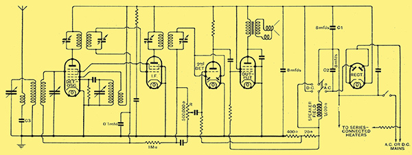
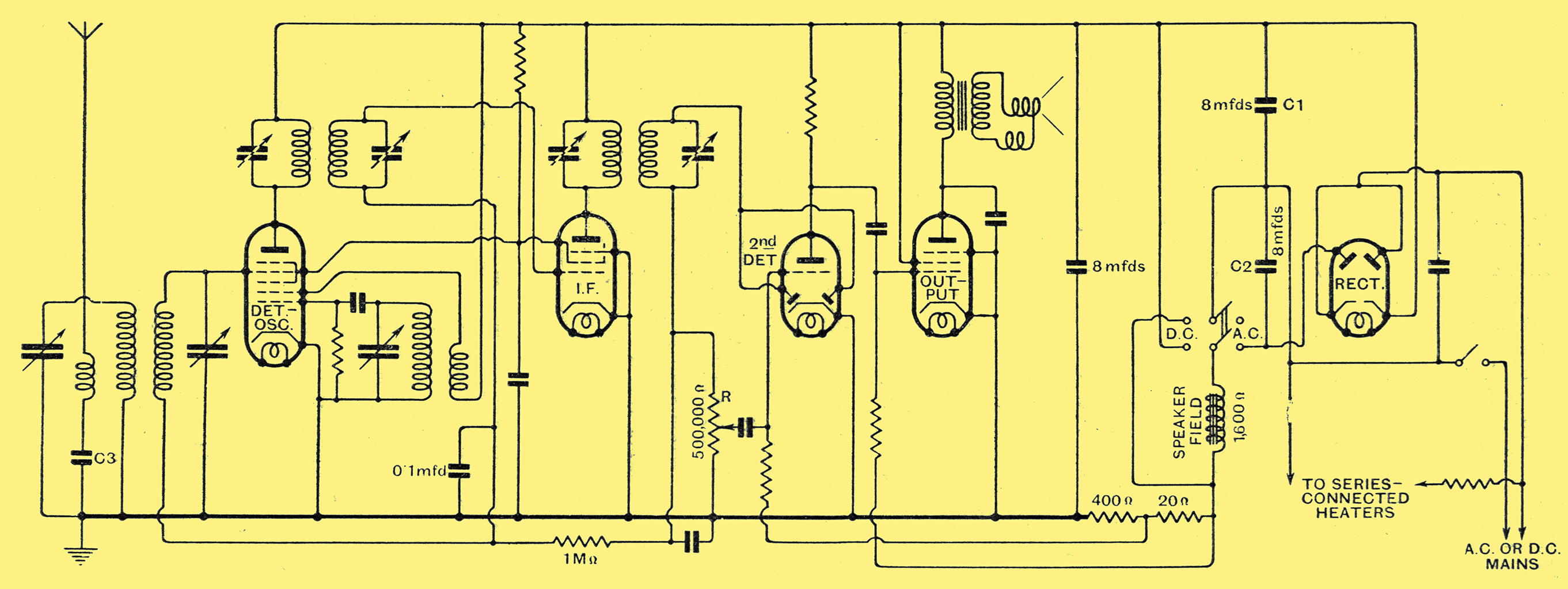
Fig. 1. - The circuit arrangement of a typical midget superheterodyne.
Fig. 1 shows the circuit of a typical midget superheterodyne. The valves all take the same heater current of 0.3 ampere, and their filaments are arranged in series, no mains input transformer being used. Instead, two rectifiers in one bulb are used; they are arranged to charge alternatively two series-connected electrolytic capacitors, C1, C2. These two capacitors tend to have a total potential across them of twice the original AC mains voltage of 110. This scheme is undoubtedly the cheapest possible way of feeding a set with HT current from 110 Volt AC mains. After allowing for the drop in voltage through the loud speaker field, which acts as a smoothing choke, the HT voltage. is of the order of 150 Volts. A DPDT switch is arranged to change from AC to DC mains. In the DC position the anode current flows through one of the rectifiers.
Two-circuit aerial tuning is used only in order to get rid of second-channel interference.
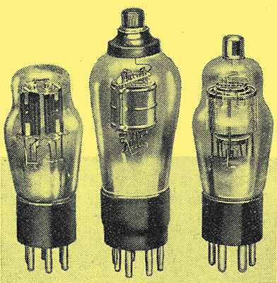
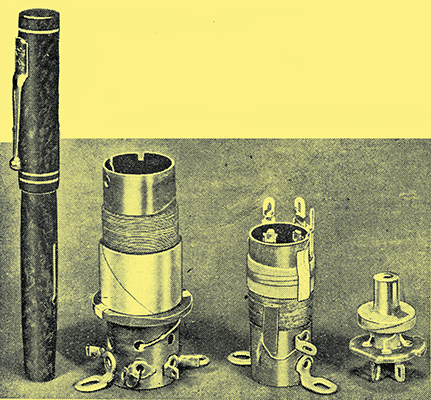
Two American valves compared with a typical British specimen, seen in the centre.
A 6A7 Pentagrid is employed as a single-valve frequency changer, and a screened pentode serves as an IF valve. To obtain adequate AVC action, both the converter valve and the IF valve must be fully controlled by the AVC voltage from maximum down to virtually zero magnification. These two valves deliver about four volts peak to the diode on fairly strong stations with the indoor aerial, consisting of a few yards of wire, which is permanently fitted to the set. The grid of the triode portion of the second detector valve is supplied with LF voltages from a tapping on the diode load resistance R. Volume control is obtained by varying the position of this tapping. The DC potential across the diode resistance is employed for AVC. The triode gives sufficient LF magnification to load the output pentode, even on very weak signals, when the peak IF Volts to the diode are much less than four.
The loud speaker has a cone of only about three inches diameter, and is often fitted with a 'hum-bucking' coil. The values of various typical components are marked on the circuit diagram. A careful examination will show that there is not a single component or connection in the receiver which could possibly be eliminated. As an instance, it might be thought that cost would be saved by employing a tapping on the aerial coil, instead of a separate aerial windings. A tapping is not used because the HT eliminator circuit connects the whole receiver directly to the mains. Accordingly, the aerial is electrically isolated from the receiver by means of the capacitor C3 and a separate aerial winding, in order to avoid danger to the user.
For operation of the set there are only two knobs, one actuating the three-gang tuning capacitor and the other the volume-control potentiometer. The latter knob also acts as an on-off switch when it is turned to zero.
The number of valves in the receiver/is at the irreducible minimum. The frequency converter obviously cannot be eliminated, while the IF valve is required not only for its magnification but for the selectivity it confers by means of its tuned output transformer.
Diode detection is essential both for AVC and to avoid detector overloading on strong signals.
With a highly sensitive British output pentode one might perhaps eliminate the triode portion of the detector valve without losing too much sensitivity, and feed the audio-frequency volts from the diode load resistance direct to the output valves. But such high-efficiency. output valves are unknown in the USA; they are probably far too expensive to be made successfully for that market, even if the American valve makers overcame the technical difficulty of obtaining a sufficiently high mutual conductance.
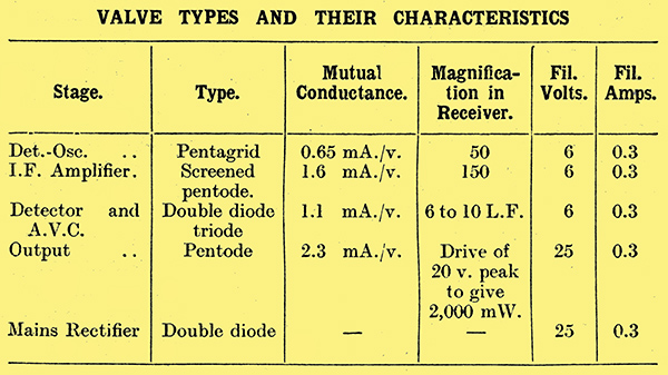
The magnification factors and mutual conductance of the valves in a typical receiver are shown in the table, and it will be seen how unfavourably these figures compare with those of British valves. The anodes of all the valves receive the same voltage of about 135, and the screening grids are fed from the same source of voltage through a resistance. They are nominally operated at about 100 Volts, but pressure varies with the application of the controlling AVC Volts. This variation is less than might be expected, however, because the screen current of the pentagrid valve increases as its grid bias is made more negative by the AVC while at the same time the screen current of the IF pentode is reduced. Therefore the total screen current of the two valves, and therefore the screen voltages, tend to remain very roughly the same for all values of AVC voltage.
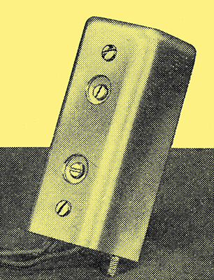
Illustrating the compactness of American components. From left to right: aerial coil; oscillator coil; single-tuned IF transformer.
Further economies are made, and a great deal of ingenuity is shown in the actual layout adopted. Even the cost of an extra coil shield is a matter of,serious moment to an American designer. The aerial and bandpass coils are wound on an unshielded former, and positioned above a metal base-board. They are just sufficiently screened from one another by a metal shield to give the desired looseness of coupling without the expense of shielding cans and extra coupling devices.
A band-pass IF transformer.
The oscillator coil and first IF coil are found not to produce whistles even if they are close together and are unshielded. But both must be shielded from the aerial input circuits. To avoid putting them in separate cans they are therefore fastened below the metal panel, which serves to screen them from the aerial coils, which are above it. The second IF transformer must, however, be shielded from all the other coils, and is therefore placed in a separate can.
The loud speaker is sandwiched in as shown, and the valves arranged compactly. It is found that only the IF valve need be shielded. The IF transformers consist of two tiny coils barely an inch in diameter, but, nevertheless, having the quite good dynamic resistance of 175,000 Ω at the standard intermediate frequency of 175 kHz.
The set described covers the broadcast band only. Other midgets include switching for shorter wavelengths, such as those employed by the police. The never-ending warfare between police and underworld is apparently a source of entertainment to a large percentage of American listeners.
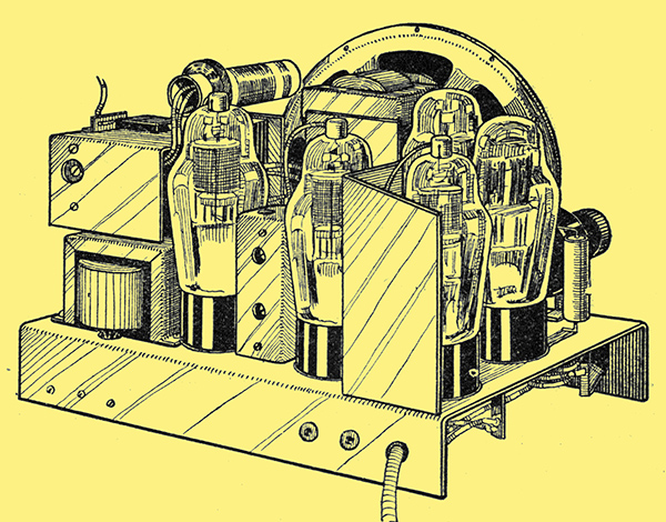
How space is saved; overall dimensions of the chassis are about 9 × 6.5 × 4.5 inches.
|