|
How the new triple-diode triode AC/HLDDD works.
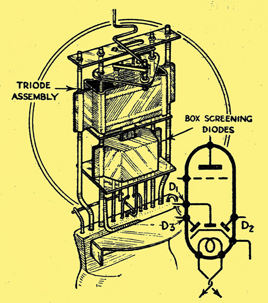
The three diodes are mounted within a screening box below the triode electrode assembly, as will be seen in this sketch, which also shows the diagrammatic symbol for the new valve.
The chief drawback of AVC is the high level of noise found during the process of tuning a sensitive and selective receiver, for when the set is not tuned to a carrier the sensitivity rises to its maximum. In this article a system of quiet AVC is described which does not involve the use of an additional valve owing to the introduction of a new type - the triple-diode-triode - which can simultaneously perform the functions of signal rectification, first stage LF amplification, and quiet delayed amplified automatic volume control.
The sensitive long-range superhet with AVC has come as a great boon to the listening public, who can now enjoy entertainment from their radio sets from one station at a time. Neither are the benefits of this type of receiver confined to selectivity and sensitivity alone. Quality of reproduction can be as good as that of the most ambitious straight set, and the ease with which 'blasting' and the effects of fading can be overcome is a virtue among many others which is leading the superhet to a position of supremacy in this country.
There is one shortcoming, however, which becomes more irritating as the selectivity increases. It is the background noise between stations, the automatic elimination of which has hitherto been expensive and has generally been found only on the most elaborate receivers. When an AVC set is tuned to a carrier wave the early valves are biased back and the sensitivity is reduced, but in the inter-carrier spaces each valve is working at its maximum sensitivity and we are treated to the full amplification of atmospherics, man-made static, valve noise and general mush.
It is no use cutting down. permanently the absolute sensitivity of the receiver, as there are times when it may be wanted, but, as a compromise, a variable sensitivity control (in addition to the usual volume control) can be embodied and set to suit the prevailing noise conditions. Such a control is a little cumbersome as it must perforce be an auxiliary to the main volume control and very seldom can be left unaltered during an evening's listening. A form of AVC is required in which all inter-channel noise, together with those programmes which are so weak as to be useless from an entertainment point of view, are completely silenced. Such a system is called quiet AVC and can be effected in either of two ways.
A mechanical relay can be provided which shunts the LF output when no carrier is present but which is actuated when the incoming signal reaches a pre-determined level. The system works best when there is an additional valve to operate the relay, but the disadvantages are the liability to mechanical derangement and the fact that it requires a rather larger carrier to bring the set out of noise suppression; than is required for suppression. The other method is to over-bias considerably the LF or detector valves and so reduce the amplification and to remove the extra bias when the incoming carrier exceeds the suppression voltage. The latter system is entirely successful but has hitherto entailed the use of an extra valve, and so is to be found only in receivers where expense is not of paramount importance.
By the introduction of the new Mazda triple - diode - triode - styled the AC /HLDDD - it is possible to arrange a circuit in which amplified, delayed and quiet AVC can each play their role, using only a single valve. This brings QAVC to the more popular type of superhet, and it would seem safe to prophesy its inclusion in a large number of next season's receivers.
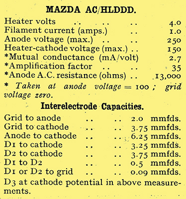
The characteristics of the new valve are given in the table, from which it will be seen that care must be exercised in connecting up the three diodes as they are not interchangeable. The heater has been specially designed to give a high insulation to the cathode so that amplified AVC can be used with impunity. In operation the three diodes and the triode are entirely independent of one another, each section being completely screened.
The circuit advocated (see Fig. 1) is ingenious, for amplified AVC is obtained in the normal way except that the diode D2 which supplies the bias to the triode does not supply the LF The detector diode D1 is returned to the delay diode D3 and both are negatively biased in the absence of a signal by the amount of the delay voltage so that no rectification occurs. When a strong enough signal is tuned in the cathode potential falls until it is negative with respect to the earth line, whereupon the delay diode-cathode path becomes conductive and the AVC starts to function. The signal diode being returned to the delay diode is now at cathode potential and rectification starts.
How QAVC is obtained
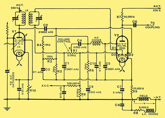
Fig. 1. - Second detector circuit giving amplified, delayed and quiet AVC with a single Mazda triple-diode-triode valve. The components C8, R8 and LFC act as smoothing and the 8,000 Ω shown in the diagram is the sum of R8 and the DC resistance of LFC.
The foregoing gives a brief summary of the fundamental processes involved, but to understand the precise mechanism the circuit must be examined in greater detail.
Let us take the diode D2 first. When a signal voltage is received from V1 it passes via C2 to the diode D2, which has a load resistance R2 returned to cathode, and is therefore always conductive. There are developed across R2 in accordance with the ordinary process of simple rectification, HF, LF and DC components, the former two being shunted away by R3 and C3 leaving a rectified DC voltage of about 0.8 × signal peak volts [★] The efficiency of the diode detector with the load shown is such that the DC output is about 0.8 times the peak HF input. to be applied as bias through R4 and the HF choke to the control grid of V2. The increased negative bias reduces the anode current of V2, which in turn, reduces the voltage drop along the cathode circuit (R5, R8 and LFC.).
Assuming the effective DC amplification of the valve to be 15, it will be seen that a signal of 3.3 peak volts at the IF transformer primary will depress the cathode potential by 40 Volts approximately, since 3.3 × 0.8 × 15 = 39.6. Should the AVC delay voltage be fixed at 40 then a signal of the amplitude just referred to will about neutralise it. A signal of 5 Volts peak, for instance, will cause the cathode potential to drop by 60 Volts (for 5 × 0.8 × 15 = 60) and the delay voltage of 40 would not only be neutralised but a negative bias of 20 Volts would be applied along the AVC line to the early valves in the receiver. This explains the amplified AVC process.
Taking the signal diode D1 next, it will be seen that it receives its signal from the secondary of the IF transformer and has the usual load resistance R1 in the return circuit. The latter is connected not to cathode but to the delay diode D3, which has the conventional AVC decoupling circuit and a load R9 joined to earth. The LF speech component developed across R1 is fed through the slider of the volume control X to the grid of V2, is amplified, and appears across R7 - the anode load so that parallel-feed LF coupling can be carried out in the ordinary way through C6. A filter (HF choke and C5) prevents the application of residual HF to the grid of the AC/HLDDD.
It has been found that a delay voltage of about 40 is the most satisfactory for this circuit, a figure which is obtained by passing the anode current of all the valves preceding V2 through the loud speaker field, and the anode current of V2 through R5, R8, and LFC. The field should be of such a value that the volts dropped are about 80, and the total cathode resistance must be 33,000 Ω, the voltage absorbed being about 120. The difference between these two, which is the delay voltage, will thus be 120 - 80 = 40. As the diodes D3 and D1 are both effectively biased negatively by 40 Volts, neither AVC nor signal rectification begins until the incoming carrier produces a cathode voltage depression large enough to, neutralise this. This explains the suppression of inputs below a certain predetermined minimum value, or QAVC.
The components R6, C9, are included to stop all signs of motor-boating which are liable to occur when a sensitive set with amplified AVC is tuned to the fringe of a carrier wave. The capacity C9 must be kept as low as possible, otherwise the time constant of the AVC noise-suppression circuit may be excessive, and weak stations will be lost while 'searching'.
It may be desirable in different localities, or at different periods of the year, to provide varying degrees of noise-suppression; that is, the actual amplitude of aerial input which will bring the set out of noise-suppression should be adjustable at will. To effect this, a control of the maximum sensitivity of the valves preceding V2 is necessary, and is provided by a variable common cathode resistance R10.
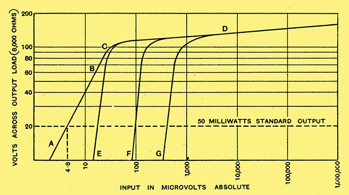
Fig. 2. - Showing the AVC characteristics of a 5-valve superhet having three controlled stages and employing a Mazda AC/HLDDD valve in an amplified, delayed and QAVC circuit.
In Fig. 2 are given curves for the performance of a five-valve superhet with three controlled stages, using a Mazda AC/HLDDD as a second detector. Curve ABCD represents the AVC characteristic without noise-suppression. From A to C there is no AVC. Near C the delay voltage is neutralised and the AVC action starts. From 100 to 1,000,000 μVolts absolute input, representing a change of 10,000 to 1, the output power change is only 2 to 1 - a very creditable performance. By making use of the noise suppression control R10 we may silence all noise, or stations whose aerial amplitude is less than E, or if more drastic suppression is needed all inputs below F or G.
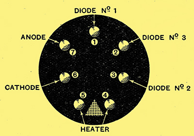
The arrangement of the pins looking at the base of the new Mazda AC/HLDDD valve. The top-cap is connected to the control grid. Care must be taken to join the diodes as shown in the circuit diagram.
|
