|
Practical details of the subsidiary apparatus required for operating the Cossor tube .
The purpose of this article is to give the reader practical information to enable him to set up a cathode ray oscillograph, with its associated apparatus, so that it can be used for a variety of experimental investigations into the behaviour of wireless receivers and other apparatus. Those readers who may not wish to acquire such an equipment at the moment will, nevertheless, be interested in understanding its operation.
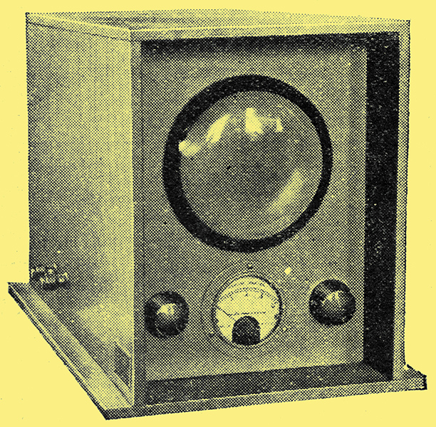
Box mounting for the oscillograph tube. The inclusion of a filament ammeter or voltmeter is essential.
Recent months have shown a rapid growth in the popularity of the cathode ray tube among set manufacturers and experimenters. The visual indication which it can provide as a guide to receiver performance reveals instantaneously many properties of a set where the more complicated method of observing by the aid of several meters and deducing the results might well be expected to take some hours. In the hands of the experimenter the cathode ray tube opens up a vast new field of interest and instruction in a manner which has no ready parallel among the meter methods of test. On the screen of the tube can be observed both the amplitude and frequency distortion which an LF signal may suffer in the process of amplification. Only the cathode ray tube can reveal the widely varying load conditions of a moving coil loud speaker due to the characteristics of its diaphragm. Response curves of HF circuits are shown at a glance instead of by the laborious system of taking innumerable meter readings. To those who aspire to the possibilities of high definition television the cathode ray oscillograph appears an essential. It can be synchronised by electrical means, thereby removing the severe limitations in picture analysis by the use of revolving apparatus.
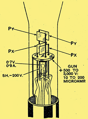
Fig. 1. - The cathode tube. Internal arrangement of the electrodes in the Cossor tube.
In this article the endeavour will be made to put into practical form constructional details of the apparatus required for operating the tube, The internal construction of a Cossor tube is shown in Fig. 1. The complete equipment may be considered as three units:-
- the tube with its mounting, 2-Volt filament accumulator, filament resistances and filament ammeter
- the high voltage eliminator which produces the gun potential and shield bias; and
- the time base unit.
Power is derived from AC supply.
The Tube Unit
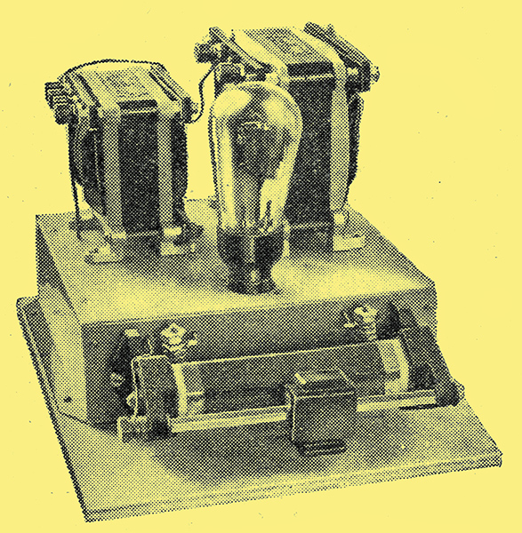
HT unit for providing the gun potential. The output is continuously adjustable up to some 3,000 Volts.
A simple form of housing for the tube is a plywood box with a hole exposing the screen of the tube. This protects the tube from damage, shades the screen and interior from light and gives accommodation for the filament resistances and ammeter, the last-named being an essential. A current of about 1 Ampere is required and. the precise value is shown on the tube used. Just over a Volt is dissipated in the pair of filament resistances which provide fine and coarse adjustment.
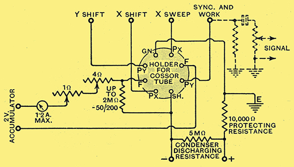
Fig. 2. - Tube holder circuit. Critical control of filament current is provided. Negative biasing of the shield is effected through a resistance in the filament to HT negative lead. The filament heating accumulator must be insulated from earth.
The pin connections and wiring are given in Fig; 2, A negative bias of some 200 Volts is applied to the shield by means of a voltage dropping resistance in the negative HT lead and takes the form of a leak resistance between the F and SH terminals. A protective 10,000 Ω resistance is included in the HT+ lead, while a high resistance effects the discharge of the smoothing capacitors of the HT supply unit.
HT Unit
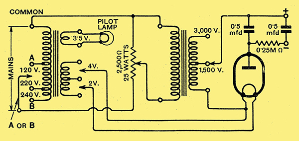
Fig. 3. - Variable voltage HT unit. Tapping points on the transformers in conjunction with a heavy duty potentiometer permit of continuous DC voltage variation from zero to over 3 kV.
Up to 3,000 Volts may be required and an almost continuous variation up to this value is provided. The current drawn is exceedingly small, so that this high voltage eliminator. is not unduly costly to construct. Rectification is by a half-wave valve and the variation of output is obtained from a pair of transformers, Fig. 3. Filament heating and HT windings are carried by separate transformers and the former by means of a centre tapping on its primary provides for halving the primary voltage applied to the latter. For normal low-voltage working the centre tapping point is used so that the 3,000 Volts indicated on the HT transformer is only some 1,500 and the 1,500 terminal becomes 750, Between the two transformers is a heavy duty potentiometer which provides further sub-division. Three terminals on the filament transformer give 2, 4 or 6 Volts so that the special 2 Volt Cossor SU130 rectifier may be used, or, alternatively, almost any 4 Volt rectifier, or, on the 6 Volts, an old RH1 or even B12 triode.
As only a minute current is drawn from the rectifier the customary smoothing choke is replaced by a high resistance. A pair of high-test voltage capacitors assembled as a single unit complete the smoothing equipment. A high-value shunt resistance affords a leak on the rectifier to avoid the capacitors retaining a charge.
If, now, the two units are connected together and the filament current cautiously advanced to the stated value, a bright spot will be obtained on the screen. For this test the Px and Py terminals are all connected to the Gn terminal. Use initially the centre tappings on the filament transformer and the secondary of the HT transformer while steadily advancing the control resistance from zero.
Time Base Unit
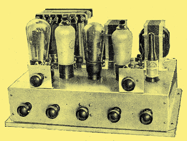
The Time Base unit. The controls are: velocity, trigger, velocity stepped capacitor, amplitude, synchronising, X shift and Y shift.
Across the Px terminals a time base potential is applied in order that the spot of light may traverse the screen on a horizontal line. The effect may be produced by the 50 Hz supply, but in this case the speed of-travel is not uniform, neither could it be varied to synchronise with the predominant frequency of the signal to be examined. The spot must journey at constant speed across the screen and then restore as quickly as possible. A capacitor charged through a resistance and discharging through a neon tube is sometimes used as a time base circuit, but this, again, is not linear, as the capacitor discharges exponentially.
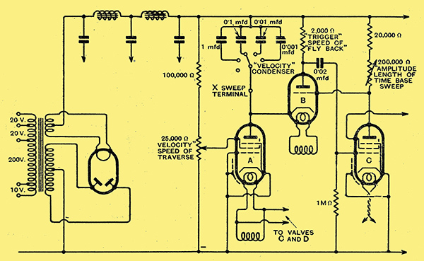
Fig. 4. - The Time Base circuit. The time taken to charge the capacitor depends upon its capacity and the adjustment of the screen potential of the A. Discharge takes place through B and is accelerated by the action of C.
A linear traverse results as a capacitor charges through a constant current device which is, in this case, an HFpentode valve (MS/Pen, MSP4 or VMP4). It is the steady rise in the potential of the charging capacitor which produces the X sweep. The rate of charge is controlled by the capacity of the capacitor, the screen potential of the pentode valve, and, to a lesser extent, the adjustment of the circuit which shunts the capacitor and provides for its almost spontaneous discharge. Fig. 4 shows the action of the time base circuit and the arrangement of the fly-back action. The cycle taking place, if briefly expressed, can be readily grasped, and the procedure is as follows:-
- The capacitor charges through the HF pentode A (MS/Pen, MSP4 or VMP4), which is operating on the flat part of its anode-Volts, anode-current characteristic. The rate of charge is governed by the setting of the screen potentiometer, and this determines the speed of traverse of the point of light across the screen. This adjustment is the velocity control.
- Current is passing in the anode circuit of the HF pentode valve C (MS/Pen, or MSP4), and the consequent voltage drop produced creates a negative bias on the grid of the triode B (41MP or MH4), the cathode of which connects to the anode of valve A. The value of this bias is governed by the variable anode resistance of C. This is the amplitude control and regulates the length of the traverse line on the screen of the tube.
- The rising voltage across the velocity capacitor is applied to the anode and cathode of B, and eventually a potential is reached where, in spite of the negativeness of the grid, anode current flows.
- By virtue of the resistance in the plate circuit of B, the flow of anode current causes the voltage to drop at its anode and it becomes less positive. This fall in potential is communicated to the grid of C, which, now becoming more negative, passes less anode current, In consequence, the negative bias of B is almost completely removed, so that the entire discharge of the capacitor can now speedily take place through the anode resistance of B. This resistance, which regulates the speed of discharge, is the trigger.
- As the discharge proceeds, the anode current of B falls, and conditions restore preparatory to the recommencement of the cycle.
Synchronising
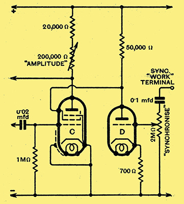
Fig. 5. - Synchronising control. A positive potential peak on the grid of D causes the screen potential of C to fall and its anode potential to rise. The negative bias on the grid of B is thus reduced, causing the capacitor to discharge. In this way the time base potential is kept in step with the 'work' signal.
The signal voltage applied to the vertical traverse, Py (usually called the 'work' voltage), may be synchronised with the time base. For instance, if the time base is synchronised with a 5o Hz supply which is also applied as the 'work' voltage, a stationary sine wave results. The additional valve D (41MP or MH4) (Fig. 5), is used for synchronising, and part of the A 'work' voltage is .applied to the grid by means of the coupling capacitor and adjustable potentiometer, and the action is as follows
- A positive impulse reaching the grid of D causes an increase in its anode current. The voltage on the anode of D, therefore, falls, taking with it the potential on the screen of C.
- With the fall of screen potential the value of the anode current through C lessens, and the anode potential rises.
- The negativeness of the grid of B with respect to its cathode is thus reduced, and the discharge of the capacitor through B is stimulated. Thus, each positive peak of the 'work' voltage throws the triggering effect of the valve B with its associated anode resistance into action. In using the synchronising circuit the amplitude control is first regulated, followed by a close synchronising adjustment by means of the velocity control. Just sufficient of the 'work' potential is then introduced by advancing the synchronising control as will hold the figure stationary.
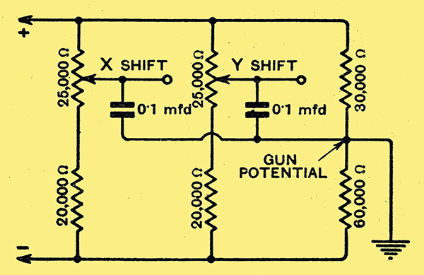
Fig. 6. - Controls for centring the image. Adjustment of the potentials applied to the X and Y plates shift the image vertically or horizontally into the centre of the screen.
Additional controls provide for suitably locating the figure on the screen. These consist of potentiometers which vary the potentials on the X and Y plates in relation to the gun potential which is the earth point in the circuit. A pair of potentiometers operating across the HT supply are used for this purpose (Fig. 6).
Some Typical Oscillographs
he successive cycles are of uniform width, showing the time base traverse to be linear. The horizontal line is the fly-back. Itsfaintness shows that the return of the spot is rapid and a brightening to the left indicates that its velocity, which is due to thedischarging of a capacitor through a. resistance, is non-linear.
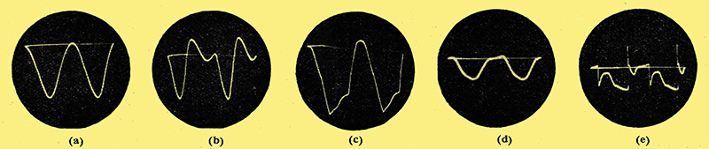
(a) Wave-form, of potential developed across the anode load of a 6 Watt triode output valve. A constant frequency is applied to the grid. - (b) The same output stage, showing the second harmonic content brought about by over-biasing. (c) Effect of insufficient bias. (d) A compensated pentode output stage. (e) Further distortion of the wave-form given by the pentode brought about by reduction of the anode potential.
|