|
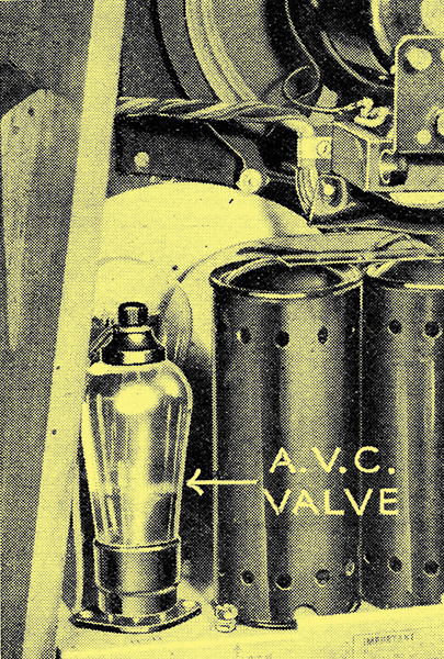
The double-diode valve is usually of the duo-diode-triode type, and in addition to acting as the second detector and providing delayed AVC it gives a first stage of LF amplification. The illustration is from the Ferranti Gloria superheterodyne.
Selecting the best operating conditions.
The various methods by which automatic volume control can be achieved are by now fairly well understood, and it is generally realised that if the initial sensitivity of the receiver is not to be reduced the control should be delayed - that is, it should be inoperative until the signal input exceeds a certain predetermined value. Although there is no mystery about the manner in which circuits of this type function, there are so many different arrangements with which AVC can be obtained that a choice is sometimes difficult. Moreover, having selected the system which is to be used, the problem of choosing the best operating conditions still remains.
The delayed diode AVC circuit is attractive on account of its simplicity, and, although it may not be the best in all circumstances for AC operated sets, it remains probably the only entirely satisfactory arrangement which can be used in DC mains and battery-operated receivers on account of the limitation in the supply voltage in these cases. For the moment, therefore, let us confine our attention to this system and examine its characteristics in some detail, particularly with regard to the determination of the correct delay voltage.
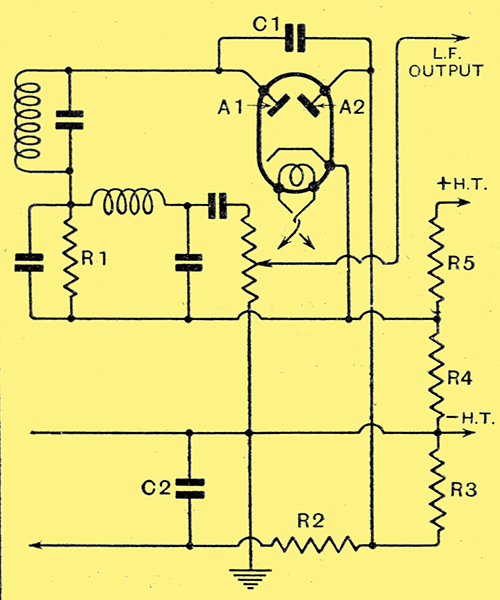
Fig. 1. - The fundamental circuit of the delayed diode AVC system, The control grids of the HF valves derive their bias through the resistance R2.
In Fig. 1 will be seen the fundamental circuit of the delayed diode AVC system in which the valve is shown as a simple duo-diode type, although it may equally well be one of the combination duo-diode-triode or duo-diode-pentode types, or even two separate triodes connected as diodes or two Westectors. The HF or IF input is applied from the tuned circuit to the diode anode A1, the cathode connection being completed through the load resistance R1. In this circuit, therefore, normal signal rectification takes place, and the LF voltages are developed across R1 and transferred through the HF filter and manual volume control to the next valve. The HF input is also applied through the small capacitor C1 to the other diode anode A2, which is connected to the cathode through the resistances R3 and R4. R3 is the diode load resistance, and usually has a value in the neighbourhood of 0.5 MΩ, While R4, with R5 forms part of a potentiometer across the HT supply. The cathode, therefore, is biased positively with respect to the earth line, and, as a result, the anode A2 is biased negatively with respect to its cathode.
The success otherwise of the AVC system depends very largely upon the amount of this bias, which is usually known as the delay voltage. Until the signal input to the anode A2 exceeds the delay voltage no rectification occurs in this circuit, and AVC is inoperative. Obviously, therefore, the delay voltage should equal the detector input obtained from the weakest signal it is desired to receive. On the other hand, if AVC is to be so effective that on the strongest signal the output to the ear is not appreciably louder, the detector input must not rise to more than twice the small input figure, for this corresponds to a change of output of only 6 dB. For this result to be achieved the delay voltage must be equal to the maximum bias required by the HF or IF stages, and this, in turn, will depend upon the type of HF valves employed and upon the number of controlled stages.
A little thought will soon show that in the general case this will lead to the detector being operated at a very large signal input, and this will mean the use of many HF stages and but little LF amplification. Whether or not this is satisfactory will depend upon many factors, of which cost is by no means unimportant.
Choosing the Delay Voltage
To put the question upon a practical basis, let us consider the choice of delay voltage for a two HF receiver, and let us assume that we wish AVC to commence when the input to the first HF valve is 1 mVolt, and that the output must not rise by more than 6 dB when the input is 5 Volts. These figures for input correspond roughly to the reception of a moderately strong foreign station and the local station respectively. For an output ratio of 2:1 or 6 dB, therefore, the input will vary in the ratio 5,000:1, or 74 dB.
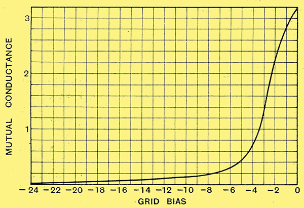
Fig. 2. - The mutual conductance of the VP4 valve for any bias voltage can be read off from this curve.
Let us suppose that we are using Mullard VP4 type HF pentodes with an anode supply of 200 Volts, and the screens held at 100 Volts, the initial bias being -1.5 Volts. The curve of mutual conductance with grid bias is shown in Fig. 2. Now in the majority of practical cases, an HF valve is operated with a load impedance of quite small value compared with its internal AC resistance, and the stage gain is then equal to the product of the mutual conductance and the load impedance when both are expressed in suitable units. Since the amplification per stage is proportional to the mutual conductance, therefore, we can for our present purposes ignore it and work directly in terms of mutual conductance. As it is much easier to work in terms of decibels than voltage ratios, let us convert the curve of Fig. 2 into one showing the drop in amplification resulting from the application of grid bias to a single valve. This is shown in Fig. 3 for one stage, curve A, and for two stages, curve B, and from this we can directly determine the bias required.
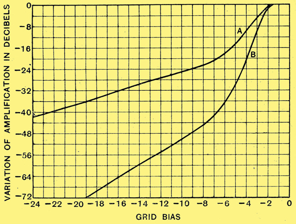
Fig. 3. - The variation of amplification with bias for one (A) and two (B) HF stages is shown here.
Since the signal input varies by 74 dB, and we permit an output variation of 6 dB, the amplification must vary by the difference, or 68 dB. Curve B of Fig. 3 shows that with two controlled stages the amplification drops 68 dB when the bias is -17.5 Volts as compared with the initial bias of -1.5 Volts. If we assume that this latter is fixed, and does not change with the HF valves anode current, we need a change of bias of 16 Volts. This will not be the case when the HF valves bias is derived from a cathode resistance, and then some 17 to 17.5 Volts AVC bias will be needed.
The HF and LF Stages
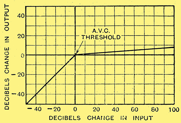
Fig. 4. - The AVC curve for the conditions laid down in the text takes the form illustrated. For signals stronger than the delay voltage, a change of input of 100 dB affects the output by only 9 dB.
For a bias change of 16 Volts the delay voltage must equal the bias voltage and also be 16 Volts. The AVC system will then come into action when the detector input is 16 Volts peak, assuming 100% rectification efficiency, and will be 32 Volts peak when the output has risen by 6 dB and the input to the first valve by 74 dB. The rectification efficiency, however, is, in practice, more nearly 85% than 100%, so that the actual maximum and minimum figures for the detector input will be nearer 37.6 and 18.8 Volts peak, or, say, 38 and 19 Volts. From the data given it is quite easy to plot the AVC curve of the set, and this is shown in Fig. 4; it is usually unnecessary to do so, however.
The design of the AVC circuit itself thus involves no difficulty; we have now to see, however, how these detector operating conditions will fit in with the rest of the receiver. In the first place, we see that on the weakest worth while signal, on which AVC just begins to operate, we have a detector input of 19 Volts peak. This gives us a DC potential across the detector load (R1 of Fig. 1) of about 16 Volts, and for 80% modulation we shall have an LF potential of 12.8 Volts peak. This is just sufficient slightly to overload a normal pentode type output valve with resistance-capacity coupling, but if we wish to use a triode we shall have to use a low-gain LF stage preceding it, for a transformer coupling does not fit nicely after a diode. In the LF circuits, therefore, there is no special difficulty provided that we use a pentode output valve.
Let us now consider the HF circuits. The detector input for a strong signal is 38 Volts peak, but during 80% modulation it will rise to a maximum of about 68 Volts. The preceding HF or IF stage, therefore, must be designed to give this output without distortion. When using an ordinary variable-μ valve such an output can hardly be obtained without distortion when the valve is biased for local reception, and the stage preceding the diode cannot, therefore, be controlled. This, in turn, involves the use of three HF stages, for it would not be possible to obtain the requisite range of control with only a. single controlled stage. With an HF pentode, however, it should be just possible to obtain the necessary output without distortion, so that we can then control the stage preceding the diode and so save an HF amplifier, unless this should be needed for amplification purposes. The inter-valve coupling is not without importance, however, for in the foregoing it has been assumed that it is of the single tuned circuit type. If a band-pass filter be used, as in many superheterodynes, the valve preceding the detector must be designed to give a distortion-less output of at least twice the maximum detector input required, or, in this case, 136 Volts peak. This obviously leads to serious difficulties with this method of AVC.
HF Stage Gain
Let us now see whether we can obtain from two stages the degree of amplification which has hitherto been implicitly assumed. The minimum detector input is 19 Volts peak, or 13.4 Volts RMS, and the input to the first valve is 1 mVolt. The amplification required, therefore, is 13,400 times, so that the stage gain of each valve must be 116 times for a total of two HF stages. Now the amplification per stage is roughly equal to the mutual conductance in mA/V multiplied by the load impedance of the valve in thousands of Ohms. The mutual conductance at minimum bias is 2.4 mA/V, so for a stage gain of 116 times the load resistance must be 48,400 Ω, or, say, 50,000 Ω. This is by no means an abnormally high figure, for even air-cored coils of the small screened type rarely have a dynamic resistance lower than this.
In theory, therefore, there is no difficulty in meeting the requirements which we have assumed. In practice, however, we may find it difficult to obtain the requisite HF amplification. It is a common experience that two HF stages with air-cored coils are unstable unless the anode connections to the coils are tapped well down, or unless unusually effective screening is adopted. It is a matter of considerable difficulty to obtain an amplification per stage as great as 116 times when two stages are employed without meeting instability problems. It is by no means difficult to obtain this amplification from a single stage, but with two stages it is another story.
It is usually more satisfactory, therefore, to adopt an AVC circuit which does not call for such a large detector input, for then we can use a smaller degree of HF amplification and make up for the reduced sensitivity by increasing the LF amplification, and in the long run this will often prove the cheaper course. In the case of a superheterodyne, however, this does not necessarily apply, for it is by no means impossible to obtain an amplification much greater than 116 times from a single IF stage, and the remaining amplification may be given by the first detector or an HF stage. Since the amplification in the different stages is obtained at different frequencies, instability problems rarely arise.
Battery and DC Sets
In the case of battery and DC mains sets there is no real alternative to the delayed diode AVC system for the reason that other methods require a source of voltage additional to the normal HT supply for their operation, and this is not usually obtainable in a convenient manner. In an AC set additional voltages present little difficulty, and we can employ amplified delayed AVC or delayed square law AVC.
It should be pointed out, however, that the difficulties attendant upon the use of delayed diode AVC are greatly reduced if the circuit is designed to give a lesser degree of perfection. If no account be taken of the local station, and the system be designed to give a substantially level output on the weakest to the strongest of distant stations, it will still counteract fading, and a much smaller delay voltage can be used with a consequent reduction in the normal detector input. This will ease the design of the HF circuits and permit a more normal value of LF amplification to be used. In order to permit undistorted local reception, however, a local-distance switch must be fitted.
There is, however, a modification of delayed diode AVC which considerably reduces the difficulties attendant upon its use. This is when the control is not confined to the pre-detector stages, but is arranged to operate also upon a variable-μ LF valve. It is then unnecessary to restrict the detector input variations to a 2:1 ratio to obtain good AVC, and a very much wider range is permissible. This in turn means that a lower delay voltage can be used with less detector input.
It will be seen, therefore, that the delayed diode AVC system is not necessarily the best, but it has been selected here for description because it is the fundamental circuit upon which most other methods are based, and because the methods of design which have been adopted are capable of simple extension to cover many other circuits. It is hoped to deal with these other arrangements in a further article.
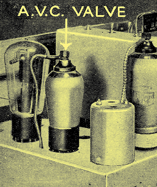
In the duo-diode-triode valve, often employed to give delayed diode AVC, the terminal on the top of the bulb is for the triode control grid. (Ekco Model 74 Superheterodyne).
|