|
The pentode is a constant current device and thus differs considerably in its behaviour when compared with a triode. It is shown in this article that if certain compensating circuits are used with the loud speaker the quality of reproduction can be superior to that from any other output valve.
The pentode is an output valve whose electrical characteristics differ very widely from those of any triode, and for this reason the problem of matching the loud speaker impedance to the valve calls for special consideration; The pentode has two outstanding advantages over the triode; first, it is capable of giving a greater output in milliwatts per signal volt input at the grid, and, secondly, the maximum undistorted output is relatively large for the amount of anode current consumed. There is a further advantage that, with certain types of loud speakers which are weak in the upper register, very effective tone correction is automatically brought into play and this can be adjusted or varied at will.
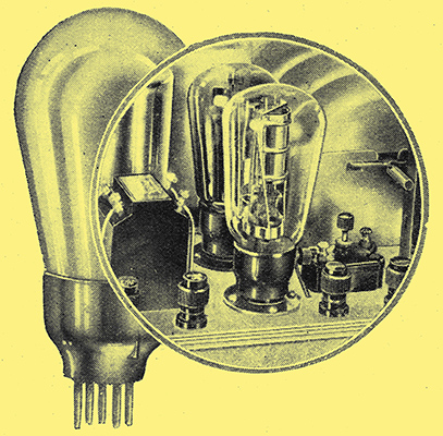
As in the case of a triode, the pentode possesses the usual anode, cathode (or filament) and_control grid. Besides these electrodes there are two auxiliary grids between the control grid and the anode. One of these is 'earthed' to the cathode inside the bulb and is the one nearest to the anode, consisting of an open spiral of wire. The next in order is the 'priming grid', also a wire spiral, but rather more closely wound than the earthed grid. This is connected to a terminal at the side of the valve base and, under working conditions, is maintained at a constant positive potential somewhat less than that of the anode itself.
AC Resistance Values
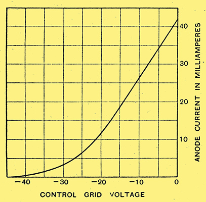
Fig. 1. - Anode current/grid voltage curves for a typical mains pentode taken at an anode voltage of 250 and screen voltage 200.
For a pentode, the curve showing the relationship between anode current and control grid voltage, with the anode and priming grid kept at normal potentials, is very similar in form to that of a triode, as will be seen from Fig. 1. But, unlike a triode, the curve is hardly affected by a change of anode volts, and it is in this respect that a pentode differs so widely from a triode in its operation. Other things being constant, if the anode voltage is increased or decreased, say, 25% above or below the normal value, practically no change occurs in the anode current.
Now, in a triode, the change of anode current is very nearly proportional to the change of anode voltage, signifying that the AC resistance of the valve is more or less constant. But where a change of voltage results in no change of current, as in a pentode, it follows that the internal impedance of the valve must vary in direct proportion to the voltage. The effective AC resistance of a pentode cannot, therefore, be stated in the same way as it can for a triode. For instance, a pentode whose apparent AC resistance is, say, 60,000 Ω, expressed as the ratio of change of anode volts to change of current, behaves in actual operation as though it has an AC resistance of only four or five thousand Ohms.
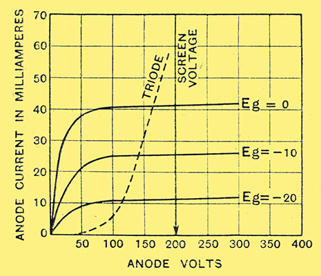
Fig. 2. - Anode current/anode voltage curves for pentode and triode, showing the difference in shape of characteristics.
The anode current/grid volts curve of Fig. 1 is not of such practical use as curves showing the relationship between anode volts and anode current for different fixed values of grid-voltage. A series of such curves for a representative pentode is given in Fig. 2, and these show clearly that, above a certain value of anode voltage, the current with any one value of grid voltage varies very little with change of anode Volts. The dotted line curve is the corresponding one for an ordinary triode output valve and is included to show, at a glance, the great difference in the nature of the characteristics for the two classes of valve.
The most suitable load impedance for the pentode is determined by considerations of the degree of harmonic distortion that may be permitted. In a triode the curvature of the dynamic characteristic curves results in the introduction of a second harmonic, but in the case of a pentode the double curvature results in the addition of not only a second harmonic but a third harmonic also, and the latter usually preponderates. The optimum load impedance is usually chosen so that the harmonic distortion, either 2nd or 3rd, does not exceed 5%. The optimum load is very much more critical for a pentode than for a triode, and for this reason an output choke or transformer with a number of tappings is used to enable the particular loud speaker used to be matched to give the best results. The usual connection with a tapped output choke is shown in Fig. 3.
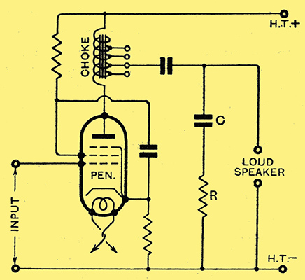
Fig. 3. - Complete pentode output circuit with tapped choke for matching loud speaker and impedance limiting device CR.
Speaker Resonance
It has been pointed out that a change of anode volts does not, to all intents and purposes, affect the value of the anode current. So, also, any change in load impedance will not affect the anode current, as it does for a triode. Now the impedance of any loud speaker varies with frequency, being usually very high at the upper end of the musical frequency scale. Consequently, when such a loud speaker is used in conjunction with an ordinary three electrode output valve, the alternating current delivered to the speaker, with a given signal voltage applied to the grid, falls off as the frequency rises. For this reason most types of loud speaker have been developed in such a way as to compensate for the falling off of current at the higher frequencies, usually by the introduction of some form of resonance.
Constant Current Device
When used with a pentode, the alternating current delivered to the speaker is the same at all frequencies, however the impedance may vary, and so, where an artificial boosting of the upper frequencies is already incorporated in the speaker design, the pentode will result in the reproduction of the upper frequencies being far too pronounced in comparison with those of the middle register, unless some means of partial suppression is provided in the electrical circuit. This correction is effected by connecting a high resistance R across the speaker terminals as in Fig. 3. Although the current supplied by the valve is constant, it divides between the speaker coil and the resistance R in the inverse ratio of the respective impedances. Since R is constant and the speaker impedance rises with frequency, it follows that as the frequency rises a larger proportion of the current will go through R and a smaller proportion through the speaker, as desired. A capacitor C of suitable value is connected in series with R to prevent the latter from by-passing any of the current at the very lowest frequencies. Practically all moving iron speakers require compensation of this nature to prevent over shrill reproduction.
Moving-coil speakers are in a class by themselves and require, from the theoretical point of view, constant current at all frequencies, and so it would appear that the pentode would be ideal for operating this type of speaker. But the theoretical conditions are not fully borne out in practice on account of diaphragm or cone resonances. As a matter of fact paper resonance at high frequencies is usually introduced purposely to compensate; for loss of high notes when used in conjunction with a triode. So a speaker with a stiff-paper cone must be compensated in the same manner as for a moving iron speaker when used with a pentode. When the cone of the moving coil speaker is made of a very soft material, no compensation is required, but in practice it is unsafe to operate a pentode without a resistance across the speaker or primary winding of the output transformer because the wide variation of valve impedance may cause dangerously high voltages to be developed during the passage of any powerful transients.
With careful matching and compensation the pentode can be made to render more realistic reproduction than a triode.
|