|
Contents
(Within the text click a heading to return here)
Introduction
Further Developments Likely
How High Note Losses Occur
Loud Speaker Losses at Low Frequencies
Why the Pentode avoids these Losses
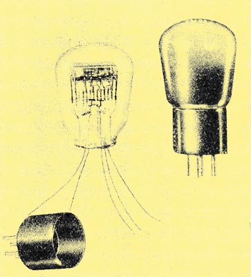
The Construction of the Pentode
Why the SG Valve cannot be used as an Output Valve
Why it can be used as a HF Amplifier
What an Output Valve should be capable of
How Secondary Emission is Prevented - The Pentode
The most important Characteristic of the Pentode
Operation
What happens in the Case of a Triode
Another Pentode Characteristic
The Output Load
The Pentode does not impose a Heavy Drain on the HT Battery
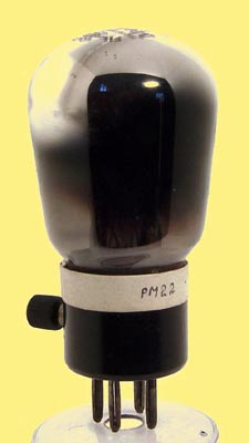
In this article one of the leading experts in the wireless industry deals with some of the most interesting characteristics of the Pentode
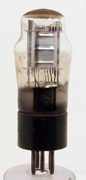
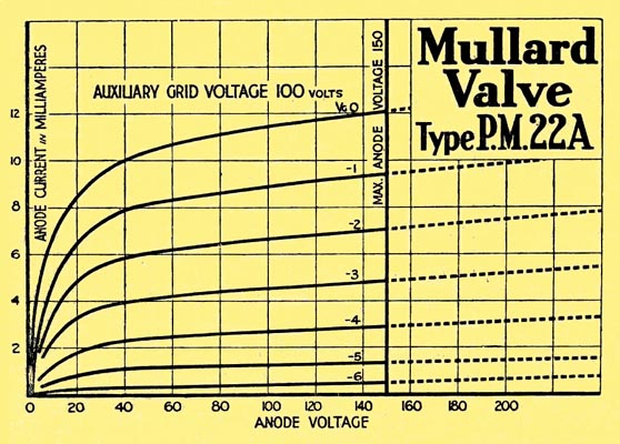
A Mullard PM22A
One of the most marked features of radio design and development during the past few years has been the attention given to the output stage of radio receivers. and particularly to the production of valves for use in that stage.
It has been realised by radio engineers that the transformation of the radio programme from audio frequency voltage variations into audible air vibrations constitutes a series of problems upon the solution of which the perfection of radio reproduction largely depends.
A noteworthy result of these researches was the development of the pentode or five-electrode output valve. This valve, particularly in combination with the latest types of speaker, provides an output stage having remarkably high electrical efficiency, and capable of a very high standard of reproduction.
As there are signs that the future may see further important developments of the Pentode, possibly the introduction of pentodes of still larger output, some description of the operation of this class of valve will be of general interest.
Before the particular virtues of the pentode valve can be appreciated, it is necessary to have a clear idea of what is going on in the loud speaker connected to the output stage.
The loud speaker may be regarded as a motor doing work on the air surrounding it and as a result of this and the copper loss in the moving coil, the whole device displays a resistive characteristic to alternating currents of speech and musical frequencies. Unfortunately, however, this is not true when the whole range of audio frequencies is considered, for the following reasons.
(a) At the higher musical frequencies, the mass of the coil and the middle of the cone plays an increasingly important part, in that it tends to prevent proper movement of the cone.
The effect is exactly equivalent to that which would be obtained if an inductance were interposed between the source (output valve) and a perfect loud speaker. Then, assuming constant A.C. voltage at the source and increasing frequency, there would be less power expended in the speaker as the frequency rises. Any free (leakage) inductance contributed by the output transformer similarly reduces the higher frequencies.
(b) At the very lowest frequencies in the musical gamut, the resilience of the coil locating device and the diaphragm surround become apparent and this also is equivalent to a reactance in series with the working impedance of the speaker, again reducing the available energy, but at the lower end of the range. This reactance is, in effect, capacitative, i.e.. the current wave leads the voltage wave and the effect varies inversely as the frequency.
From (a) and (b) above, it will be seen that some attenuation is inevitable at both extremes of the musical scale if a triode output valve is used, which can be regarded as a generator with a substantIally constant emf since the current through the coll decreases at the highest and lowest frequencies.
It is one of the outstanding advantages of the pentode valve that, over quite a wide range of external impedances, it is a constant current device. This is due to the fact that the differential internal resistance, generally called 'impedance' (not a scientifically accurate description of the quantity) is commonly many times greater than the impedance presented by the load (the loud speaker), thus the valve itself largely determines the magnitude, of the speech currents in the stage.
It follows that the reactance effects mentioned earlier, due to what might be termed mechanical reactances, are no longer, harmful when a pentode, is used, as the increased impedance results in a relatively small decrease only in the load current.
The pentode valve is a development of the screened grid tetrode now universally used for high frequency and amplification, and we shall see how the special requirements of the output stage necessitate the special pentode form.
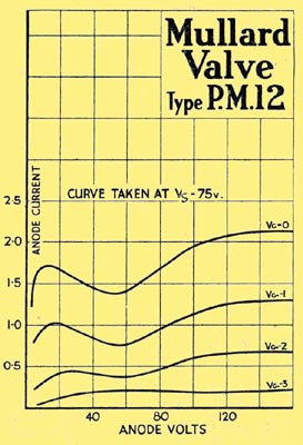
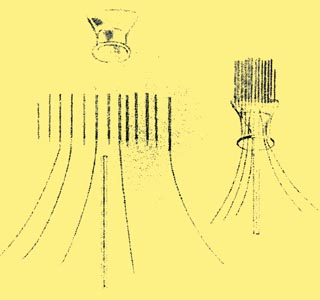
Referring to the curves for the PM22A and the PM12 above, it will be seen that for the PM12, which is representative, there is an initial rise of anode current with voltages up to approximately 20 volts, after which there is a negative resistance portion, i.e., that part of the curve where an increase of the anode voltage results in a reduction of anode current. This effect which stops before the anode voltage becomes equal to the screening grid voltage, is due to secondary emission from the anode back to the screen grid. Finally, when Va is much greater than Vs, we get a linear characteristic of high differential resistance, i.e. deltaVa / deltaIa is large.
Why it can be used as a HF Amplifier
This part of the curve is useful for amplification purposes, since various changes of the control grid voltage result in almost exactly corresponding changes of anode current. The initial kinks in the S.G. characteristic are not disadvantageous in a HF amplifier, for the input HF voltages will range from about 10 microvolts to perhaps 50 millivolts, resulting in changes of anode volts up to about 5 volts RMS (7 volts peak) in an extreme case. Such a variation is clearly permissible without departing from the linear portion of the curves.
What an Output Valve should be capable of
The most desirable feature of the output valve, however, is that it must be capable of large variations in anode voltage and current, without reaching the region of curved characteristics, and this is clearly impossible with the simple SG valve. To remove the hills and dales from the tetrode characteristic it is necessary to prevent the back-emission from anode to screen mentioned earlier and the most obvious way of doing this is to remove the anode some distance from the other electrodes.
How Secondary Emission is Prevented - The Pentode
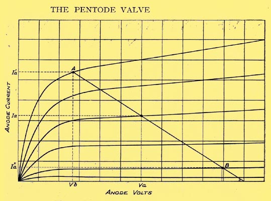
There are, however, certain disadvantages attached to this method, notably bulky construction and a somewhat serious diminution of Ia before the hump is ironed out. Accordingly, the desired characteristics are brought about by interposing a third grid, of open mesh and fine wires, between the normal auxiliary grid and anode, which is joined to the cathode (or the middle of the filament in a directly heated valve). This effectively prevents any secondary anode emission, and we get the type of characteristic shown above for the PM22A.
The most important Characteristic of the Pentode
As pointed out earlier the pentode is substantially a constant current device, and inspection of the characteristic curves reveals that there is little variation of Ia over the major part of the range of anode voltage. It is this part of the characteristic which is used in the output amplifier.
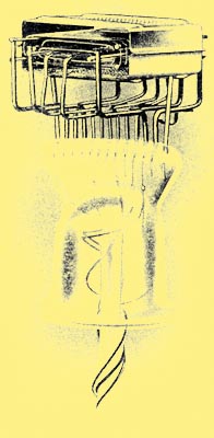
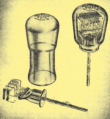
Operation
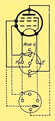
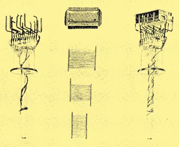
Showing the arrangement of pentode terminals
One of the attributes of the pentode is high sensitivity and this again is really due to the constant current feature.
When the output stage is excited by the application of a signal to the control grid, large variations of anode voltage take place, because the A.C. voltage produced by the signal is, in effect, superimposed on the battery volts, being in opposition to the battery volts during one half. of each cycle and assistant in the other. For example, a small output valve having 150 volts steady potential at the anode might display fluctuations of plus or minus 100 Volts. That is, the anode potential might vary between 50 and 250 volts.
What happens in the Case of a Triode
Now, in the case of a triode, the phenomena producing these fluctuations tend to cancel in the following manner: The steady battery voltage is split up between the valve and the load, which are of comparable impedances and when a positive impulse is impressed on the grid, the anode current increases, i.e., the apparent resistance of the anode filament path drops, which results in a reduction of anode potential. The resultant increase of anode current will therefore not be so great as would be expected from the applied impulse alone. Similarly, the energy stored in the loud speaker during positive half cycles produces a rise of anode voltage when the grid receives a negative impulse, which tends to prevent the anode current decreasing to the low value expected during such impulses.
Another Pentode Characteristic
Curves of a hypothetical pentode
Further examination of the pentode characteristics shows that an increase of anode current will not be checked by, falling anode volts, and vice versa, as the Ia/Va characteristics are nearly horizontal. Reference to the image above and also to the hypothetical curves shown below will make this point clear. It is assumed that the two valves, of which the Ia/Vg curves are shown have equal slope or mutual conductance. The operating curves are shown as full lines and the normal static curves dashed. The three static curves are shown in each case for the same anode voltages but for one auxiliary grid voltage in the case of the pentode, as this voltage, which largely controls the anode current, is unvarying during operation.
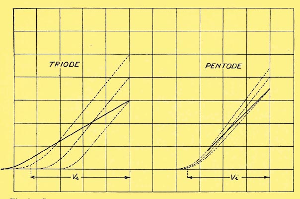
Showing that an increase of anode current will not be checked by falling anode Volts
Vi represents the peak input swing to be applied in each case, and it will be seen that this is materially less in the case of a pentode.
The Output Load
It is well known that the impedance of the load in the case of a triode valve bears a direct relation to the so-called valve impedance, varying in practice between equality and four times that of the valve for the limiting cases. No similar direct relation exists in the pentode case, where the load is usually less than the valve impedance.
The Pentode does not impose a Heavy Drain on the HT Battery
The pentode valve, which was first introduced to the British market by the Mullard Company, in 1928, has achieved a remarkable degree of popularity. At first available only in forms suitable for use in battery-operated domestic receivers, they now comprise an extensive range, including a small pentode operating at the low anode consumption of 4.5 milliamps, at 100 volts; large types for all battery receivers; directly and indirectly heated AC mains pentodes; and high voltage pentodes giving outputs of several watts, and suitable for use in the largest radio gramophones and in medium sized public address equipments.
|