|
Automatic volume control, in its popular application to broadcast receivers, is of comparatively recent date. Naturally the first applications were to receivers for telegraphy reception, and here it did not matter if the control was effected on the modulated signal after detection. For the reception of music, however, it is desirable, in order to avoid a flattening out of the reproduction, that the automatic volume control should operate on the strength of the carrier wave and be unaffected by the degree of modulation.
Although automatic volume control is comparatively new as applied to broadcast receiving sets, it ranks as a more or less time-worn expedient in the older arts of line telegraphy and telephony. That is to say, so far as its application to the problem of 'fading' is concerned.
The conductivity of a line-wire. changes considerably under different climatic conditions. Extremes of temperature and of moisture produce different attenuation losses, which must be compensated if a reasonable level of speech or signal strength is to be maintained.
Perhaps the first solution was to provide a separate pilot line, through which control signals were sent from time to time, in order to allow the amplification at repeater stations to be supervised manually and readjusted as and when required. Some fifteen years ago a system was developed in which this operation was performed automatically by means of a variable potentiometer arranged in the input circuit of the amplifier valves. As telephone lines are usually grouped together, it is a simple matter to set aside one circuit for control purposes.
An Early Scheme of AVC
The pilot line forms one arm of a Wheatstone bridge, which is provided with a polarised relay across one diagonal and a source of EMF across the other. Any abnormal change in attenuation unbalances the bridge and brings a small motor into operation to shift the potentiometer tapping until the new conditions have been met.
A system of this sort is not, of course, suitable for broadcasting where one is dealing with a modulated carrier wave instead of ordinary LF signals. Also, it must be borne in mind that alterations in the ether channel, such as those which give rise to ordinary fading, occur much more rapidly, and erratically, than the slow climatic variations which are the chief concern of the line engineer.
In broadcast reception the common practice is to utilise the rectified carrier-wave as the source of a special biasing voltage, which is.led back to control the sensitivity of the HF stages. The signal or modulation components are, in general, not suitable for this purpose, because they tend to flatten out the pianissimo and fortissimo passages to the same dead level of sound. Of course, if a sufficient time delay is included, the modulation components may help to cope satisfactorily with slow fading, such as is met with on some of the longer wave stations.
A noteworthy attempt to utilise the detector output to control the performance of preceding HF valves dates from 1923, and although originally devised as a means for reducing 'static' and other interference in a commercial wireless telegraph system, it appears to disclose the fundamental principle of automatic 'gain' or volume control as utilised to-day in broadcast sets.
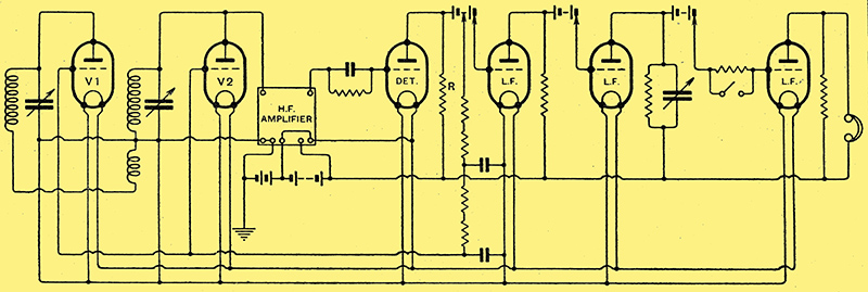
Fig. 1. - A circuit dating from 1923, where the output from the detector is made to control the performance of HF valves.
As shown in Fig. 1, the voltage developed across a resistance R in the output of a leaky-grid detector valve is led back to bias a pair of valves V, V2 connected in shunt to the aerial and tuned input circuits. The result is to apply a variable damping to these circuits as the anode-cathode resistance of the auxiliary valves V1, V2 is altered by the change in the grid bias.
Principle of Operation
Heavy atmospherics-or a strong interfering signal which tend to throw the grids positive, will reduce the internal resistance of the valves V1, V2, and so diminish the efficiency of the input circuits. In effect, the arrangement gives a certain degree of automatic volume control, though not specifically designed for this purpose.
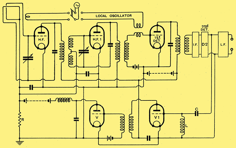
Fig. 2. - A circuit of 1925 where the amplified output, after rectification by the valve V, is applied to control the grid bias of HF stages.
Perhaps the first definite attempt to tackle the problem of fading along modern lines is that shown in Fig. 2, which dates a couple of years later, in 1925. The circuit is a superhet, and energy is taken from the second detector stage D2 by a series circuit L, C tuned to the intermediate frequency, and fed to an amplifier V1. The amplified output is first rectified by a valve V and then applied through a resistance R to control the grid bias of the high-frequency stages HF and HF 1. Here the rectified carrier-wave is definitely used to effect automatic control, and may in fact be used to suppress any signals below a predetermined value which is, of course, the principle QAVC.
From this point progress becomes more rapid, and in 1926 We find a system in which the control voltage is used to bias a valve functioning as a variable impedance in one arm of a Wheatstone bridge. The input is applied to one diagonal, and the output is taken from one of the arms of the bridge through a transformer. Here, again, the primary application is to line telephony, but the object of attaining a uniform high-quality transmission over a wide frequency band is deliberately kept in view.
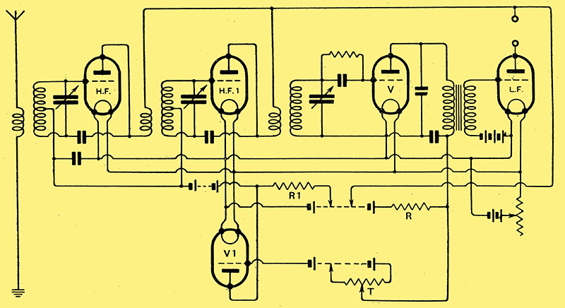
Fig. 3. - The AVC valve V1 is operated by voltage changes on the detector anode.
In the same year we discover an appreciation of the desirability of combining 'visual' tuning means with sets fitted for AVC and also a disclosure of the use of a 'diode' rectifier for obtaining both signal and AVC voltage from the same valve. Further, it is shown how the principle of AVC may be applied to eliminate the effect of fluctuations in the main supply voltage.
Since 1927 the number of circuit arrangements designed to provide AVC have been legion. In some cases 'mechanical' control is utilised, but mostly the control is wholly electrical. The former type is hardly suitable for ordinary broadcast reception, since the small power available demands the use of very delicate instruments.
One illustration may bperhaps be given, in which a milliammeter is inserted in the output circuit of the detector valve and is fitted with a moving vane, which also forms one of the vanes of the aerial tuning capacitor. This, on the face of it, is more ingenious than practical.
The electrical systems are almost entirely based on the principle of varying the grid bias on the HF valves, using the rectified carrier-wave for the purpose. Here the depth of modulation affects the output to some extent, i.e., a station with 80% modulation gives a signal twice as loud as one with only 40% modulation.
In some cases the output from the LF amplifiers has also been utilised, although, as previously stated, this tends to soften loud passages and strengthen weak ones unless the control is deliberately 'delayed', in which case it is ineffective for 'rapid' fading or when the set is tuned through a strong station. The period of 'delay' is fixed by applying the control voltage to a capacitor through a series resistance, so that the time taken by the capacitor to charge comes into account.
Owing to the tendency to produce cross-modulation, the use of a variable grid-bias did not in practice prove very satisfactory prior to the introduction of the variable-μ valve. Even with the variable-μ valve, AVC to be a really practical proposition demands a generous range of control voltage, of the order of 40 or 50 Volts, as compared with the 5-10 Volts originally used with the ordinary screen-grid type of valve.
|