|
This article is based on the above book.
Automatic volume control AVC, or automatic gain control AGC, as it is sometimes called, is a system for keeping the volume from the loudspeaker at a constant level, no matter what the strength of the high-frequency signal strength may be. Manual volume control - i.e., by hand - is usually fitted even on sets provided with automatic volume control, since although it may be desirable that all stations should come in at the same strength on the loudspeaker, yet one obviously wants to be able to control that strength to suit personal requirements.
The main object of AVC is to make it unnecessary to keep altering the manual volume control as one passes from station to station. In the ordinary way, one may readily receive a local station at tremendous strength, while a few degrees away on the dial another station may be comparatively weak. As one tunes still farther round the dial, a very powerful station may produce a most unpleasant blare. There is an obvious advantage if all the stations can be brought in at full loudspeaker strength, but no louder and no weaker. For Tuned Radio Frequency TRF or straight sets this is done by altering the sensitivity of the whole set, either on the high-frequency or on the low-frequency side, or on both; while in the case of super-heterodynes, detectors and intermediate frequency amplifiers may also have their sensitivity adjusted to increase or decrease the sensitivity of the set as may be required. This is done by altering the working point, and thus the amplification offered by, variable-μ valves.
In 1933 many wireless sets were home constructed and simple TRF sets were the norm. Also the BVA restrictions on multiple valves and the tax on the number of valve-holders in a commercial set also kept the TRF as the main design philosophy. Thus many types of detection were in use and in the book Scott-Taggart describes them. As the 1930s progressed and the superhet became the standard model of receiver design most sets were commercially manufactured and the complexity of setting-up was taken care of with professional equipment. Thus having a double diode triode at the end of the IF chain became standard.
However, in the 1930s an interesting method of AGC and demodulation was based on a special valve as follows.
Wunderlich Valve for AVC
See Unknown for a suitable valve
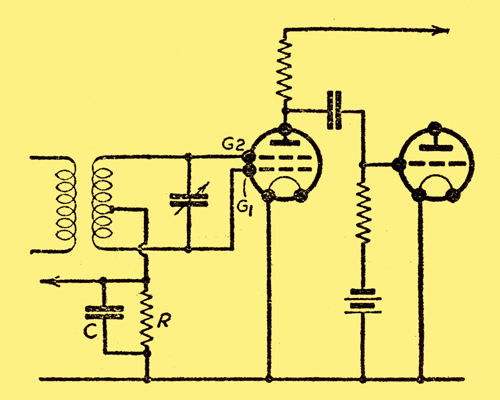
A special valve has been developed in America for AVC work, and the circuit is illustrated above. The valve consists of two grids G1 and G2, which are interlinked so that each is the same distance from the filament, and between that electrode and the anode. The grids are, therefore, symmetrical, and each end of the tuned circuit is connected to a grid, while the middle point of the inductance is connected through the grid leak R and capacitor C to the filament. The operation of the arrangement is as follows:
The two grids and the filament form a full-wave rectifier, which supplies a generous rectified current, which passes through the resistance R. The result is that a fluctuating potential is set up across R corresponding to the LF current from the microphone at the transmitting station, and these LF potentials are applied to both grids. As far as LF is concerned, therefore, the two grids are given the same potential variation, and as they are interlinked (although not touching, of course) they act in the same way as would a single grid, and produce an amplified low-frequency current in the anode circuit of the valve. The DC and AC components of the current through R are made use of as follows: The AC component produces voltage variations across R which are communicated as just described to the grid, while the DC component is smoothed out by the usual resistance and capacitor (not shown) before being applied to the grid of a variable-μ HF amplifier.
Delayed AVC with Double-Diode Triode
In this circuit one anode is the detector the other produces an AVC voltage.
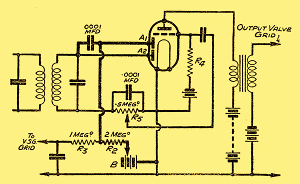
Use of the double-diode triode is illustrated in above where one of the diodes of the double-diode is utilised for AVC, while the other is used as a diode detector. It will be seen that the anode A2 is connected to the top end of the inductance, the bottom end of which is connected to the usual 'grid leak' R5 of, say, 0.5 MΩ and grid capacitor of 0.0001 μF to the cathode. A tapping is taken on the resistance R5 to the grid of the valve. This is simply the ordinary arrangement of a diode followed by an LF amplifier.
The tuned circuit, however, also feeds the anode A1 through a fixed capacitor of 0.0001 μF which serves as a stopping capacitor. The anode A1 is now connected through a resistance R2 and a bias battery B to the cathode. When the input high-frequency current communicated to A1 exceeds the negative voltage of the bias battery B, an electron current will flow from the anode A1, down the vertical thick line in the diagram through the resistance R2 and round to the cathode. In doing so, there will be a DC component flowing through R2, and use of this rectified carrier-wave is made by filtering out the LF variations by means of a resistance R3 and a capacitor of, say, 0.1 μF capacity. The DC component is then fed to the grid of the variable-μ valve. The circuit is quite simple to understand if one divides it in this manner. The object of the bias battery is to provide an initial voltage on the anode A1, so as to produce a delayed AVC action which comes into force only when signals reach a predetermined value. The bias voltage is adjustable, and in practice would be derived from a potential divider (usually a moving contact on a self-bias resistance).
In later years with AC mains as standard and the phasing out of DC mains the standard design for AGC and AM demodulation was of the form shown below.
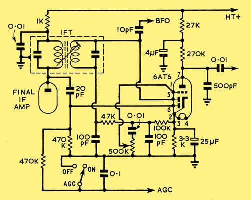
AM detector and AGC rectification based on a 6AT6 valve.
|