|
A simple explanation
In discussing the valve curves reproduced in the accompanying figure the best starting-point will be a mental picture of the processes going on within the valve.These start at the filament, which, when heated by the passage through it of the filament current, emits a stream of particles of negative electricity. These are known as electrons, and are distinguished by the property of being attracted towards any positively electrified object and repelled by any that is negatively electrified.
The flight of the electrons after they are ejected from the filament is controlled by the potentials applied to the other electrodes- grid and anode contained within the valve. The anode is positively electrified by being connected, through the anode-circuit components, with HT plus, while HT minus is connected to the filament. The grid, on the other hand, is usually made negative to the extent of a few volts, a small battery or its equivalent being interposed between it and filament for this purpose.
Being negatively charged, the grid will tend to repel electrons back into the filament, even in spite of the fact that the plate is positive. The latter, owing to its greater distance away and to the fact that it has to exert its pull through the meshes of the grid, has much less effect on the movements of the electrons just after they have left the filament than has the grid.
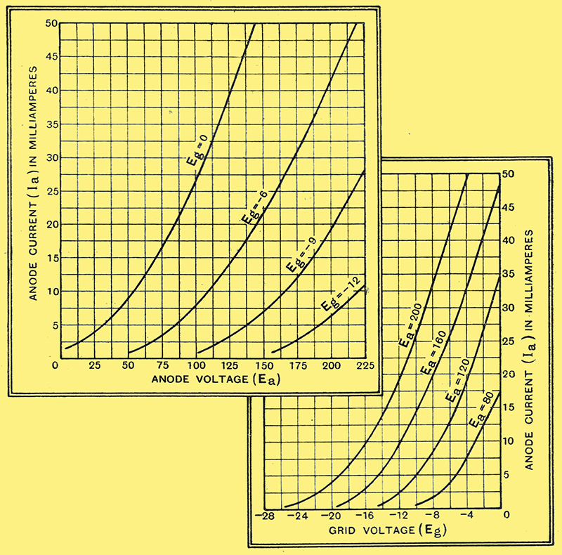
The two different types of valve characteristic generally issued by manufacturers. That on the right is used for mutual conductance calculations, while that on the left gives the amplification factor and AC resistance.
If we compare the curves connecting grid voltage Eg with anode current Ia, the greater effect of the grid can be seen quite clearly. With an anode voltage Ea of 200 Ia (the anode current) is 26.5 mA. when Eg = -10 V. If now the anode voltage is reduced to 160 Volts, taking us on to the next curve on the diagram, the anode current is reduced to 14.5 mA. The reduction in voltage at the anode has reduced, as one might have expected, the number of electrons reaching it in any given time. By making the grid more positive it will repel less firmly the electrons in the space between it and the filament, so that more will pass through its meshes and reach the plate. The anode current can therefore be restored to the original value of 26.5 mA. by decreasing the grid bias. Running the eye along the curve for Ea = 160 leads to the discovery that the grid voltage corresponding to the anode current we want is -6 Volts.
Amplification Factor
For the particular valve to which these curves refer it is therefore clear that a decrease of 40 Volts on the anode can be compensated by making the grid 4 Volts less negative. It follows that grid and anode are so constructed and so positioned that a change of 1 Volt on the grid has the same effect on the anode current as a change of 10 Volts on the anode itself. This ratio, namely 10:1, is known as the amplification factor of the valve, and is usually represented by the Greek letter μ.
How this ratio defines amplification can best be seen by considering the anode-voltage/anode-current curves, each of which refers to the fixed value of Eg marked against it, and gives for that bias the variation of anode current with changing anode voltage.
Suppose, now, we were to insert in series with the anode of the valve some device (e.g., a choke) that would hold the anode current constant, and then swing the grid voltage rapidly up and down - say from 0 to -12 Volts. It we began by setting the valve at Eg = -6 and Ea = 150, the anode current would be 22 mA., as the curve shows. On rapidly swinging the grid voltage between the limits mentioned, the anode voltage would have to change according, to the curves it the current could not alter, the whole process would be expressed by a horizontal line at the height 22 mA. in the diagram, and stretching from the curve for Eg = 0 to the curve for Eg = -12. The anode voltage would therefore swing between the limits 85 and 205 Volts, a range of 120 Volts. This represents 10 Volts per one Volt swing on the grid, so that the experiment has resulted in amplifying the voltage supplied to the grid 10 times amplifying it, that is, by the figure we have already found for μ.
Another important property of the valve can be directly deduced from the anode-current / anode-voltage (Ia/Ea) curves we have been discussing; On the curve for Eg = -6, the anode current corresponding to Ea = 150 V is 21.5 mA., while that corresponding to 200 V is 41.5 mA. An increase of anode voltage of 50 Volts drives an extra 20 milliamps. through the valve. By Ohm's Law its resistance in thousands of ohms must therefore be 50/20, which comes out at 2,500 Ω. This is the AC resistance, or impedance, of the valve, and specifies the resistance the valve offers to a small alternating voltage superimposed on the steady voltage of the HT battery. Clearly the numerical value depends on the inclination of the curves, being lower as the curve gets steeper from which, seeing that none of the curves have the same inclination over the whole of their length, We infer that the AC resistance of a valve depends on the operating voltages applied. With a triode these variations are trifling, in practice the change in resistance is small over the regions used in practice, but with other valves notably screen-grid valves, the variations are much greater.
The third characteristic of the valve, mutual conductance or slope, symbolised by g, is derived from those already discussed. It is shown best by the Eg/Ia curves from which the term slope is derived. Over the straight portions of these a change in grid voltage of one Volt induces a change in anode current of about 4 milliamps. (On the curve for Ea = 200, Ia = 49.25 at Eg = -4, and 33.25 at Eg = -8. A change of 16 mA for 4 V, or 4 mA per grid volt.) The mutual conductance can also be found by dividing the amplification factor by the AC resistance; in the present case μ/R0 = 10/2,500, which is 0.004 Amps, or 4 milliamps per grid Volt. This will be seen by remembering that, by Ohm's Law, one Volt change on the anode will alter the anode voltage by 1/2,500 Amps, or 0.4 milliamps. Since, by the definition of amplification factor, one Volt on the grid is equivalent to μ Volts on the anode, the change in anode current provoked by altering grid bias by 1 Volt is μ times that due to a one Volt change on the anode.
|