|
Explaining the standard symbols.
As a topic of interesting discussion valve legs may have its rivals, and some readers may even feel that an apology is due for introducing the subject. When, however, it is remembered that the number of electrodes in the case of some valves has been nearly doubled in the last few years, readers - especially those who have lately taken up wireless may indulgently agree that a brief survey of the present position is useful, if not absolutely necessary.
The recent introduction of the variable-mu amplifier both for batteries and mains, the indirectly heated mains rectifier, the mains pentode with independently heated cathode, calls for new symbols when these valves are shown in a circuit diagram. Another development is the metallisation of HF and detector valves a valuable asset with modern high-amplification sets.
Reference to the diagrams where the standard connections are given schematically, reveals that there are ten different valve symbols in general use, and, while there are other semi-obsolete types existent, it has not been considered worth while to include them. Next to each symbol, and to the photograph of a typical valve of its class, is a sketch giving the relative pin positions when looking at the base of the valve with the bulb remote from the observer.
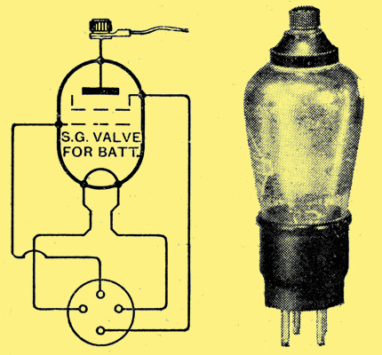
Cossor 220SG Battery SG valve.
Taking the valves in the order in which they would be used in a receiver, the battery screen-grid valve would come first. As high-frequency energy is here being amplified, it is essential that the terminals and internal leads to the anode and grid should be spaced as far apart as possible. This has led to the standardisation, in this country, of the anode terminal at the top of the glass bulb and of the control grid terminal in the normal position in the base. The screening. grid is connected to the pin which would ordinarily be the anode in a three-electrode valve. It is usual to employ metallised SG valves, the advantages conferred being a reduction of anode-grid capacity and the prevention of unwanted external coupling.
When looking at the base of a battery metallised valve and turning it so that the control grid is 'north', the filament pin which is connected to the metal coating, and so should be joined to LT minus and earthed, is 'west'. Should the 'eastern' filament pin (grid being north), be taken to LT minus and the coated bulb of comparatively large area inadvertently allowed to touch any earthed metal screen in the set, the LT battery will be short-circuited.
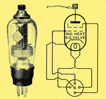
Mazda AC/S2 Mains SG valve.
All mains screen-grid valves, both for DC and AC supplies, are now made with indirectly heated cathodes as the directly heated type have not proved successful. The contact pins have the same relative positions as those of the battery SG valves, the heater connections taking the place of the filament leads and the cathode or emitter being brought to an extra pin the centre of the base. To prevent stray fields, which would probably cause hum, the leads which carry the heater current are usually twisted together, as shown in the symbol for this type of valve. Mains SG valves are available metallised for the same reason as battery SG valves, but it must be remembered that the large area of metal coating increases the anode filament capacity, and any capacitor used to shunt the cathode bias resistor should be non-inductive. Metallised mains valves have the metal coating connected to the cathode pin, and an accidental short-circuit of the cathode bias resistance must be avoided.
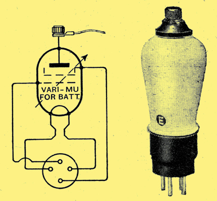
Cossor 220VSG Battery variable-mu.
The new variable-mu valves are essentially screen-grid valves in which the control grid wires are not uniformly spaced. The effect of this is to produce an HF valve with a mutual conductance which varies over a wide range with change of control grid bias. (It should be noted that variable-mu is an abbreviation of variable mutual conductance and not of variable-μ or amplification factor).
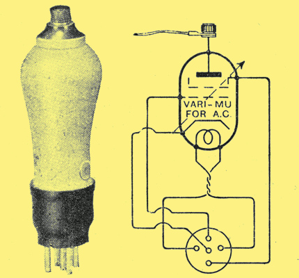
Osram VMS4 Mains variable-mu.
To represent this large change of overall amplification which the valve exercises, an arrow is used across it which, as a symbol, has come to mean a continuously variable control. The notes concerning contact-pin disposition and metallisation of the ordinary SG valve apply equally to variable-mu valves.
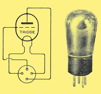
Mullard PM2A Battery triode.
Of the triode which has been with us for so many years little need be said beyond the advent of metallisation where the working impedance is above, say, 8,000 Ω, so that detectors and first LF valves may benefit from efficient valve screening.
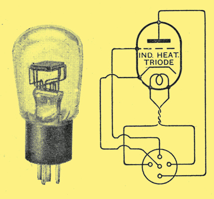
Mullard 354V Mains triode.
The indirectly heated triode has a fifth pin in the centre of the base connected to the cathode.
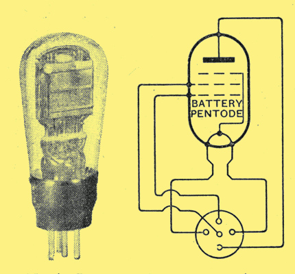
Mazda Pen220 Battery pentode.
Taking the pentode next we find that its connections are somewhat confusing and care must be taken in the wiring of the valve holder. Whichever type is considered, the anode, control grid, and heater or filament pins are the same as those of the triode already discussed, but with the battery or mains directly heated pentode the auxiliary grid is brought out to the centre pin in the base corresponding to the cathode connection in an ordinary mains valve.
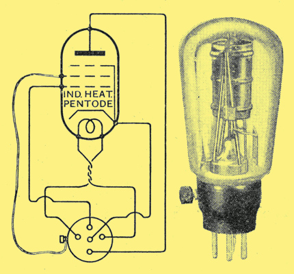
Mazda AC/Pen Mains pentode.
The indirectly heated pentode always contains a centre base pin for cathode connection and a side terminal on the base for the auxiliary grid. Should, therefore, a directly heated pentode with five base pins be replaced by an indirectly heated type also with five pins, the cathode will receive some 200 Volts in excess of its requirements. Before making the change the centre socket of the valve holder should be connected to the bias resistor and the disconnected lead joined to the side terminal.
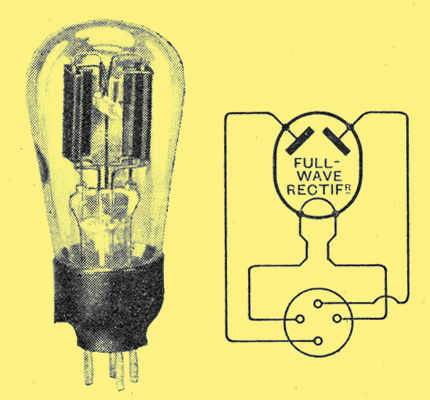
Osram U12 Full-wave rectifier.
With regard to AC mains rectifiers, the full-wave valve is by far the most popular. It contains two anodes, one being joined to the pin which is normally the control grid and the other to the anode pin. Considerable interest attaches to the indirectly heated full-wave rectifiers, which not only have an increased capacity for overload, but, by reason of the slow heating of their emitters, no dangerous surge voltages are developed when switching on and smoothing capacitors are safe-guarded from breakdown. The cathode in these valves is internally connected to the heater.
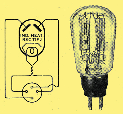
Mazda UU60/250 Indirectly heated rectifier.
With so many valve types and such a multiplicity of connections we owe a debt of gratitude to the Valve Manufacturers Association that standardisation is complete. For the same class of valve any makerbs product will have contact points in the same relative positions.
|