|
Not as simple as they seem.
A service engineer's job is to rectify faults that occur in sets. To rectify is to put right. So he could be described, in a sense, as a rectifier. But if we go into a wireless dealer's and ask for a rectifier we get something quite different. As a technical term it means something that passes current in one direction but not in the other, or, at any rate, not nearly so readily. The mechanical equivalent is a valve (for example, the thing that lets air into a tyre but not out). That is how the radio valve got its name. Oddly enough, the rectifier is the only valve in a set that is not counted as a valve (Superhet Seven do Whatnot six valves excluding rectifier). That is just one of the paradoxes of radio terminology. I could fill a page with them and did, a year or two ago. Most of the things in the set that are called valves - those intended tor amplifying - are arranged with immense care so as not to rectify at all, for rectification is distortion, and the name 'valve' seems singularly inappropriate for them. Apart from the 'rectifier', the only genuine valve is called something still different - the detector. Logically there seems to be no reason why it should not be called a rectifier, too, for that is what it is; but in practice it is very convenient to have a name - even if rather a silly one - to distinguish it from the power rectifier.

Fig. 1. These symbols, for half-wave and full-wave rectifiers respectively (either power rectifier or detector), are deceptively simple ....
To look at a rectifier valve or its symbol in a circuit diagram (see Fig. 1), or the data on it in The Wireless World Valve Data Chart, you would think it very simple and very dull compared with other valves having anything up to six grids apiece. But it has unsuspected depths of character, and to this day is still able to give the highbrow mathematicians something to do.
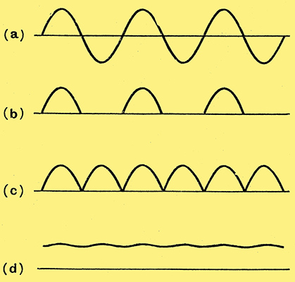
Fig. 2. .... and so are these diagrams so beloved by the writers of textbooks.
The object of a rectifier, of course, is to convert alternating current to direct. To use the tyre inflation analogy again: in pumping, the hand (or foot) moves the piston backwards and forwards, and if there were no mechanical rectifier in the system the air would just do ditto, and one could go on pumping ad lib without useful result. Remove the tyre valve and see. The valve converts the alternating air current into a unidirectional current capable of inflating the tyre. Take up any elementary chapter or article dealing with the rectifier, and as likely as not you will see something like Fig. 2, with some such explanation as (a) is a sine wave representing an alternating current. The effect of a rectifier is to suppress the negative half-cycles, leaving only the positive (b), or if a second rectifier is used in a full-wave circuit both halves of the cycle can be used (c); to avoid excessive hum this current is smoothed by a suitable filter, giving nearly pure DC (d). All very nice in its way, but quite unlike what happens in practice.
Explanation:-
- shows an alternating current all right, which is very simple mathematically (i = Imax sinωt is the equation); and
- shows what would happen if a perfect rectifier working into a pure resistance load were used, though what one would do with it then I can't imagine.
Even (b) is complicated enough mathematically. I certainly don't remember what it is, except that an infinite series or something is needed. But what happens in a mains power unit, for example, is not represented by any such simple process as, rubbing out everything below the centre line in Fig. 2 (a). The good old bicycle pump is much more instructive. When the piston is pushed down for the working stroke there is not a current of air going into the tyre all the way (except, perhaps, during the very first stroke in blowing up a flat tyre). What actually happens is that you push against a constantly increasing pressure until you reach almost the end of the stroke, and then there is a sudden quick squeak as the air rushes in for a fraction of a second. Similarly with a rectifier. The smoothing capacitors maintain a back pressure like the air in the tyre and it is only when that is exceeded by the supply voltage that current flows. When it does flow, it is for such a short part of the whole cycle that it has to be an extremely large current to get enough into the reservoir capacitor for running the set throughout the cycle. The less hum-causing ripple that can be tolerated the closer the back-pressure is to the fully charged voltage of the capacitorr, and the shorter and more intense the current. A picture of it would look more like Fig. 3 than Fig. 2 (b).
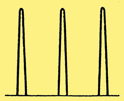
Fig. 3. The waveform of rectifier current in practical cases is usually more like this.
Obviously, then, one requirement of a rectifier for supplying a smoothed output is the ability to pass a very heavy momentary current. Other things being equal, a half-wave rectifier has to pass twice as much as a full-wave. Some of the early rectifiers for AC/DC sets had a short life for that reason. It the emission of the cathode is too small to carry the full required peak current, the supply voltage that should be pushing against the back pressure expends itself on the rectifier, which is rapidly destroyed. So it is more disastrous to under-run a rectifier filament than to over-run it. A long time ago, when such mistakes were, perhaps, pardonable, a manufacturing company put out a valve rectifier for battery charging in which the rate of charge was controlled by a filament rheostat. They all came back!
The Reservoir Capacitor
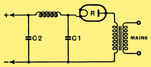
Fig. 4. Simple half-wave rectifier and smoothing circuit. If the capacitor C1 is excessively large it puts a strain on the rectifier.
Modern rectifier valves are remarkably robust electrically, and can pass almost unlimited current in brief spurts, but even they cannot be expected to enjoy many happy returns of their birthday if the reservoir capacitor (C1 in Fig. 4) is too large. Eight μF is normal, and if extra smoothing is required it is better to add it to C2. And for the reason already given it is important to see that the rectifier heater really gets its proper voltage.
The next thing is that measurements of current and voltage are very tricky in circuits where rectifiers work. This is no place to enlarge on the whole subject of peak, mean and RMS values; but granting that they are all different, one or two things stand out. The peak voltage of a supply is over 40% more than the RMS voltage (which is what is marked on the household meter, and counts for things such as lamps and heaters and wireless sets). But current is squirted past the rectifier into the reservoir capacitor at the peak voltage. So on paper it looks as if one is getting more out than one puts in - always a very unlikely proposition in the long run. For instance, you pay for electricity from the mains at, say, 200 Volts, and, without any step-up transformer, you get well, not 280 Volts DC, for there is always some loss, but probably quite a lot more than 200. Where is the catch? Just that electric power is reckoned by voltage × current, and it necessarily happens that the conditions that enable the output voltage to be higher than the input (namely, a large reservoir capacitor, so that the rectifier current only occurs near the voltage peak) lead to a highly peaked current as shown in Fig. 3. And the RMS method of reckoning goes against one here, for it leads to a higher figure than the smoothed DC output. Swings and roundabouts!
Measurement Difficulties
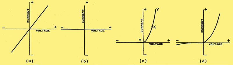
Fig. 5. Characteristic curves of (a) an ohmic resistance, (b) a theoretical perfect rectifier, (c) an actual rectifier, (d) an enlarged view around the point O in (c).
If you put two milliammeters of different types in series with the rectifier R (Fig, 4) you may get considerably different readings. This does not mean that one or both of the meters is inaccurate. One instrument may read mean values and the other RMS, and with a waveform like Fig. 3 they differ quite ta lot. Volt-meters - especially valve voltmeters used for measuring the output may similarly show discrepancies. And there are other complications. Rectified current is neither AC nor DC, but a sort of hybrid of both so be prepared for funny business when measuring rectifier circuits.
So much for meters. The other rock on which the partially informed technician stands is Ohm's Law. And that, too, crumbles into loose sand where rectifiers are concerned. If one draws a graph of current against voltage for an ordinary resistance obeying Ohmbs Law, it is a straight line such as Fig. 5(a). The slope of the line indicates the resistance a steep slope means a small resistance. A perfect rectifier would have a characteristic as shown at- (b), which indicates an infinite resistance to negative voltages and zero resistance to positive voltages. Obviously, Ohm's Law knows nothing about this. In an actual rectifier of the vacuum-valve type the infinite resistance is nearly true, but the forward resistance is generally of the order of a few hundred Ohms, and the type of characteristic is very familiar (c). The characteristic curve of an amplifying valve is usually much the same, which may be thought to mean I was wrong in saying that it is not a real valve (i.e., rectifier) at all. But an amplifying valve is normally worked at some such point as that marked X, so for a limited distance on each side it approximates to the Ohmbs Law resistance (a).
A metal rectifier, made of oxidised copper discs, has a perceptible leakage in the negative direction; but this is so small that it hardly shows on a diagram if the scale is the same as for the forward direction.
An ordinary neon lamp passes different currents according to their direction, and therefore is intermediate between Fig. 5 (a) and (c); it is a partial rectifier, and hardly good enough as such for any practical purposes. Anything with a resistance characteristic that departs at all from absolute straightness is to that extent at rectifier. However carefully an amplifying valve is adjusted to the 'straight' part of its characteristics, they never are perfectly straight, and so there is a certain amount of rectification of the signal. Rectification is distortion, as I said before; and that is why one puts a moving-coil milliamp-meter in series with the anode circuit of an amplifying valve to indicate distortion. A moving-coil meter responds only to DC - that is to say, the rectified part of the valve's output. Unless distortion is excessive, therefore, the pointer should remain nearly motionless. This does not apply to 'Class B' systems, where two distortions are balanced against one another. Obviously, if two rectified outputs such as Fig. 2 (b) were put together, not as at (c) but with the second series below the line, the original form of wave shown at (a) would be reconstructed.
No doubt some of you are putting two and two together - the detector is a rectifier, rectification is distortion and saying, 'What, then, is a distortion less detector?' No, I am not caught out by that, for the input to a detector is radio frequency, and this is distorted most fear- fully - harmonics are not limited to the usual 5%, but are more like 50%; but, in spite of this, the precious modulation will emerge pure and clean so long as the part OY of the curve (Fig. 5 (c)) is straight.
Other Rectifiers
Apart from 'the rectifier' and the detector, there is another sort of rectifier commonly used in receivers, though not everybody might know it as such. The two sorts already mentioned are the valve and the copper-oxide. The latter is quite often used for power rectification, and more rarely as a detector. The difficulty about it as a detector is that, unless the discs are very small, their capacity upsets the circuit. A third type of rectifier that was considerably used at one time for HT supply, the electrolytic, has a very large capacity indeed. It turned out to be a bad rectifier, compared with the other types, but quite a good capacitor, so is now made in millions for that purpose!
The story of rectifiers is far from complete, but my space is. I only just mention the popularity of the metal rectifiers in AC test meters, and, by magnifying the bit of its characteristic near the starting point (Fig. 5 (d) ), show how for very weak currents it is a high resistance, and for strong currents a low resistance; so by putting a pair of rectifiers of suitable size in parallel with an ordinary DC milliamp-meter it still reads small currents nearly as well as before, but can also take a very large current-perhaps 1,000 milliamps or more - without being driven violently off the scale and sent to the makers for repair. Moreover, no range switch is needed. Some day people will discover how useful this idea is; information on how to put into practice was given in the issue of January 11th, 1935.
|