|
Optimum mutual conductance depends on circuit constants.
The evolution of radio technique has proceeded, on the whole, more rapidly than has our ability to explain mathematically, or on occasion even qualitatively, the many and complex phenomena which characterise the art. The thermionic valve itself possesses circuit properties no less involved than those of the associated circuits. When in addition it is realised that these circuit properties are of importance both to the internal functioning of the valve and to the design of the external circuit, it will hardly seem surprising that it is usually easier to design circuits round valves than valves round circuits.
It is true, of course, that in many cases valves are designed to meet circuit requirements, and successfully so. But it must not be forgotten in this connection that the circuit engineer, in attempting to design a circuit round a given valve, and finding the valve has certain limitations, may say to the valve manufacturer, 'Can't you do this or that?' and so help the valve manufacturer to achieve optimum design. This is more particularly true in the case of a valve which serves a double function, such as a triode-hexode.
As is well known, the limitations of triodes as amplifiers at radio frequencies are due, first, to Miller effect, which causes a large capacity to be thrown across the grid/cathode terminals of the valve, and secondly to the fact that the effective resistance across these terminals may be negative, depending on the anode impedance and on the frequency. In a formula which will be given later the optimum slope of a triode under certain conditions is found to be considerably below that which can be obtained in practice. The same formula when applied to a tetrode or pentode gives an optimum slope which in a typical case is twice that of the triode. These conclusions are of the kind that we also find experimentally; and it may therefore be said that the use for high-slope triodes would seem to be severely limited and that the question of our title can be answered in the affirmative only in the case of valves in which the control grid is well screened from the anode.
Now although the above facts concerning triodes and pentodes are fully appreciated in a qualitative sense by the majority of radio experimenters, considerable mystery as to the exact mechanism at work still exists. For example, it is popularly supposed that the phenomenon of electron damping is important at very high frequencies only. It is, however, important at even the lowest radio frequencies - not in its damping effect on the input signal, but in another connection altogether. In order to understand where previous theories went astray it is necessary to recall the out-of-date but still very prevalent remark to the effect that the valve consumes no power from the input circuit and thus acts as an amplifier of voltage, and not of power. This notion was first dispelled by the discovery that, at medium and high-frequencies, the effect of the anode circuit impedance made itself apparent across the input, terminals of the valve to an extent depending on the grid/anode capacity and the degree of amplification taking place. The introduction of the screen grid removed the great majority of such feedback, and the old notion was revived. In other words, the screen grid and pentode valves were supposed to consume no power from the input circuit. With the appearance of papers on transit time theory a modification in this view took place, but only for high-frequency applications was it considered necessary to include across the grid/cathode terminals a resistance, the value of which varied inversely, as the product of the square of the frequency and the mutual conductance. The value of this 'electron loading loss' resistance works out so high at medium-wave frequencies that its damping effect on the input circuit is quite negligible, and as this point is of major practical importance it is perhaps, not unnatural that any other possible effect resulting from the presence of this admittedly high resistance has not hitherto been considered.
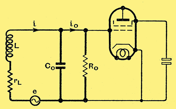
Fig. 1. Equivalent valve input circuit.
In Fig. 1. we show a generator e corresponding to some radio frequency voltage picked up by the coil L, a resistance rL which represents losses in the coil and associated eddy current and dielectric losses appertaining to the input circuit excluding valve, a capacity Co in parallel with (e, L, rL) and a resistance Ro. The capacity Co includes the capacity between grid and cathode + screen (N.B. screen is connected to cathode via a large capacitor, as shown). The resistance Ro includes the loss due to electron damping and that due to dielectric and other losses inside the valve. To summarise, the generator e, inductance L and resistance rL are external to the valve, Co is partly external and partly internal, Ro is entirely internal to the valve. In order to make this as clear as possible the electrodes of the valve are shown in thin line. The by-pass capacitor between screen and cathode is also shown in thin line.
Let us now divide the current i from the generator into two parts: a current io, passing through Ro and a current (i - io) passing through Co. Then if vo, denote the voltage across Ro we have three expressions for vo, corresponding to the three parallel branches. Now if in the circuit of Fig. 1 the resistance Ro and the capacity Co were independent of the frequency, it is easy to see that the voltage across Ro would become less and less as Ro is reduced from infinity downwards, whether the circuit be tuned to resonance or not.
In reality, however, the resistance Ro is dependent on the frequency and also on the mutual conductance gm of the valve, while Co includes the capacity Ccg between cathode and grid of the valve, which in turn changes if we make changes in the mutual conductance of the valve.
Interdependence
We thus see that, in studying the effect of changing Ro we are studying also the effect of varying Co and gm, and it will be appreciated that the theory becomes complicated.
A solution has, however, been obtained in the case where changes in gm are made by simultaneous changes in grid/cathode spacing and grid pitch in such a way as to keep the anode current constant. In other words, we will suppose that we have commissioned a valve maker to supply a range of valves of different mutual conductances, but all having the same anode current, and that the changes in mutual conductance from valve to valve were effected by means of changes in grid/cathode spacing and grid pitch only, the position of screen and/or anode remaining unchanged.
We now plug these valves in one after the other, and tune the circuit to resonance each time, observing with a valve voltmeter the voltage developed across the grid/cathode terminals of the valve as a result of a constant injected RF voltage at e in Fig. 1. Theory shows that the valve which possesses the slope given by
gm = (3Ci)/(20Co rL) × 1,000 mA/V .... (1)
will have maximum voltage developed across its input. The value of gm thus determined will be referred to as the optimum mutual conductance. It is only intended to apply on the basis of a given anode current consumption, as explained above, moreover special valves with auxiliary (secondary emission) cathodes are excluded from this argument. These have much less damping (i.e., higher Ro for a given gm, as the current taken from the cathode can be much lower, the anode current being made up largely of secondary electrons. It may, indeed, be that the secondary emission valve will eventually displace ordinary valves, but at the present time the cost of manufacture, is the limiting factor. An illuminating article by two members of the Philips Research Laboratory appears in the March issue of The Wireless Engineer, in which a mutual conductance of 50 mA/V is quoted as a practical possibility.
We will now seek the optimum mutual conductance of triodes and tetrodes on the basis of our formula (1).
- Triode. Here Co will include considerable grid/anode capacity due to Miller effect. Taking Co = 10Ci, We have gm = 15/rL mA/V. The resistance rL, may vary between, say, 1Ω for a very small low-loss coil to several hundred Ohms for a pancake coil. Highest value of gm is seen to be 15 mA/V, lowest considerably below 1 mA/V. It should here be mentioned that the optimum value of gm as defined in this article is definitely pessimistic, since the anode current change due to a signal vo, is a maximum, not when vo is a maximum but when (gmvo) is a maximum. Theory gives, however, no maximum for (gmvo) i.e., as gm is increased (whether at constant anode current or no) gmvo increases indefinitely, until, that is, the valve has become incapable of handling the voltage vo as it will do if we go on closing up the grid winding in order to keep the anode current constant. For this reason we have chosen to define our optimum gm in the way we have.
- For a tetrode or pentode, the grid/screen capacity can be at least as small as the grid/cathode capacity. Allowing for strays equal to Ci itself (which, it will be remembered, excludes strays), the smallest value of Co/Ci which could arise in practice would be about 3 with no tuning capacitor and 4 with a tuning capacitor set at minimum. Taking Co = 5Ci as typical, gm = 30/rL (mA/V), i.e., just double the figure obtained for triodes.
One result which emerges from the theory is that for low-loss coils, particularly small-size low-loss coils, the optimum gm is higher than for high-loss coils. The physical significance of this result is, roughly speaking, as follows. The apparent resistance of the valve must to some extent 'match' that of the input circuit. If we were seeking the transfer of maximum power rather than maximum voltage across the resistance Ro the matching would have to be perfect, that is to say the dynamic resistance of the tuned circuit must be equal to Ro. We are, however, more interested in maximum voltage since we can measure this more readily.
In conclusion, we may say that analysis shows that the optimum valve slope, or mutual conductance, for use with any particular circuit depends intimately on the constants of the circuit. The theory is too complex to enable general rules to be laid down, but I have tried to give some indication of the main results.
|