|
The experimenter with electromagnetic deflection is often surprised to find very high voltages appearing on the line deflection output valve, in spite of its being operated from a supply of a few hundred volts only/. The reason for the appearance of these voltages is given in this article.
At one time electrostatic deflection of the electron beam in the cathode-ray tube was almost invariably adopted for television purposes. although this method is still widely used, electromagnetic deflection is becoming more popular. With this system deflection is obtained by passing saw-tooth currents through coils mounted outside the tube and around its neck, whereas with the electrostatic method saw-tooth voltages are applied to plates mounted inside the tube.
This is no place to enter into the relative merits of the two rival methods; each has its own advantages and disadvantages. A great point is often made of the fact that with electromagnetic deflection the time-base can be run from a low-voltage HT supply in fact, the same supply as the receiver. It is true that high-voltage equipment is reduced to a minimum and that only one high-voltage capacitor and lead are required, but too much importance should not be attached to this. Although the time-base operates at a low voltage it usually consumes a more than proportionately heavy current, and in spite of the HT supply being low, very high voltages appear at certain points.
A time base for electrostatic deflection usually operates at about 1,000 Volts, takes some 20 mA., and gives a push-pull output of about 1,000 Volts p-p. The HT power is thus 20 Watts, the mean anode voltage of the valves is of the order of 500 Volts, and the peak potential 750 Volts. A magnetic time-base, however, probably takes 100 mA at 300 Volts, or 30 Watts. The applied anode voltage of the output valve is only 300 Volts, but the maximum peak potential may be several thousand volts!
At first this may seem unbelievable, but it is nevertheless true. It is, however, difficult to see how voltages, which ,may easily be ten times the supply voltage, can appear on the, anode. The effect is caused by the waveform of the signal and the nature of the anode circuit load impedance.
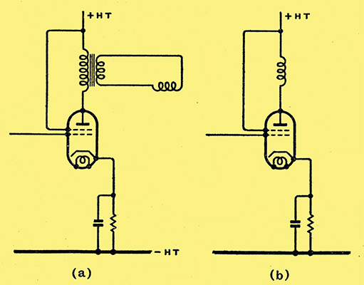
Fig. 1.The conventional output circuit of the line time-base is shown at (a) and the equivalent circuit with the coil connected directly in the anode circuit of the valve at (b).
The usual circuit is shown in Fig. I (a) from which it can be seen that the deflecting coil is fed from a tetrode or pentode valve through a transformer. This is necessary to keep the mean anode current out of the coil, for if it were allowed to flow through the coil it would deflect the spot off the screen of the tube. For the moment, however, this can be ignored and the simpler circuit shown at (b) considered. Here the coil is directly in the anode circuit.
The valve forces a saw-tooth current through the coil. In passing it should be noted that the voltage waveform on the grid is not necessarily of saw-tooth shape. The grid voltage necessary depends on L/R where L is the coil inductance and R is the resistance, including the valve anode AC resistance. If L/R is large, the grid voltage must be of rectangular waveform to give a saw-tooth current through the coil; if L/R is small, the grid voltage must be of saw-tooth waveform; if L/R is moderate, the grid voltage must be more complex and consist of a combination of rectangular and saw-tooth waveforms.
It is usually easiest to generate a sawtooth voltage wave, and in practice L/R is made small by making R large. Hence the use of a tetrode or pentode output valve; its AC resistance is often further increased by an appropriate form of negative feed-back.
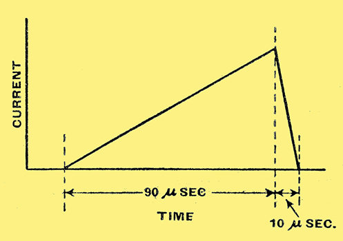
Fig. 2. An idealised saw-tooth waveform is shown here with a linear stroke and fly-back.
In Fig. 2 is shown the ideal line scanning waveform. The current rises steadily for 90 μS. for the line stroke and then falls back in 10 μS. for the fly-back. (These figures are approximate only, for the line time is taken at 100 μS. for convenience; it is actually 1/10,125 sec. (405 line TV)) Now when the current through an inductance changes a back EMF is generated in such a direction as to oppose the change of current. This back EMF e = -Ldi/dt where L is the inductance in Henrys, and di is the change of current (amperes) occurring in an infinitesimally small interval of time dt (seconds). With the particular waveform of Fig. 2 the changes of current are linear so that we can take the total change of current over the total time in which it occurs.
To fix our ideas, let us suppose that the coil inductance is 0.5 H. and the current change 100 mA. Over the line scan the back EMF is e = 0.5 × 0.1/0.00009 = -556 Volts. If the output valve is operated at 300 Volts, its anode potential would be - 256 Volts. On the fly-back, the change of current and the inductance are the same, but the time is 10 μS; hence, the back EMF is 5,000 Volts. With 300 Volts anode supply the anode potential becomes + 5,300 Volts!
Peak Voltage on the Valve
In practice, of course, these particular conditions could not arise, for the anode potential cannot become negative during the line scan. If the valve were driven hard in an endeavour to obtain a 100 mA current change, a much smaller current would be secured and the waveform would be distorted. In general, the anode potential cannot swing below +50 Volts, and with tetrodes and pentodes it is as well to limit it to +100 Volts. For the current and inductance we have assumed, therefore, the minimum HT voltage for the valve must be 656 Volts and then the peak anode voltage will vary between +100 Volts and +5,656 Volts.
In actual practice the peak voltage will be even higher because the current on the fly-back is not linear but exponential; at the start of the fly-back it changes more rapidly and the peak voltage is proportionately higher. At the end of the fly-back, of course, the current change is slower and the peak voltage is lower.
In a practical case the conditions depend on the tube, its anode voltage and the coil design. The above example was selected at random for illustrative purposes and does not fit normal practice. In general, a pentode is used taking 70 mA. at 300 Volts. If the minimum anode potential is 100 Volts the back EMF on the line scan must be 200 Volts, so that with a linear fly-back the peak anode voltage will be 300 + 1800 = 2,100 Volts. In practice it will be greater because of the exponential fly-back.
Now if the valve is to be reasonably linear we can hardly let the minimum anode current fall below 15 mA; the total change in anode current is thus 2(70 - 15) = 110 mA. We can now work out the maximum inductance for the coil; we have 200 = L × 0.11/0.00009 or L = 0.00009 × 200/0.11 1.8/1.1 × 10 = 0.164 H.
For deflection we require that the magnetic field shall change by a given amount in a given time. The magnetic field is proportional to the ampere turns - that is, to ni where n represents the turns and i the current. The inductance, however, is proportional to the square of the turns, and the back EMF to the inductance. It is thus only possible to reduce the back EMF by using a lower inductance coil and increasing the current.
Reducing the Coil Voltage
Thus, in the above example we have for a linear fly-back a back EMF of 1,800 Volts, a current of 110 mA., and an inductance of 0.164 H, for which n turns are needed. Suppose we wind the coil with n/10 turns, the current must become 1.1 A for the same magnetic field, and the inductance will be 0.00164 H. Consequently the back EMF will be 180 Volts only (ten times the current, one-hundredth the inductance).
Such a coil can be fed from the valve with a 10:1 ratio transformer, as in Fig. 1(a). Conditions on the valve are unchanged, and the same back EMF appears on its anode, for the coil voltage is stepped up to the valve by the transformer. A transformer, or choke-capacitor, feed must in any case be used to keep the mean anode current out of the coil, and by using a step-down ratio in the transformer the peak voltages in the coil are reduced. This is important, for it is difficult to secure high insulation in the coil, since it must be as compact as possible to secure the desired field with the minimum current. The insulation requirements are transferred to the transformer primary; Where they are more easily met.
The back EMF on the valve can only be reduced by using a valve passing a heavier anode current so that the saw-tooth current can be greater and the effective anode circuit inductance less. This is uneconomical, and in practice one chooses the smallest current possible subject to the back EMF that the valve will stand. The precise conditions depend upon the tube, its anode voltage and its coil design. A tube with a small deflection angle, which means either a small picture or a long tube, operated at a moderate anode voltage, can with good coil design be operated by a valve taking only 30-40 mA anode current. On the other hand, some of the new short tubes have such large deflection angles that at least 70 mA is needed.
The linear fly-back upon which the calculations have been based does not occur in practice, and it gives the minimum value of back EMF. The exponential fly-back causes much higher voltages, and in practice steps must be taken to reduce them. The fly-back time can be 15% of the line time without harm to the picture, and a slightly greater time does not have a very bad effect on the picture. It is undesirable, however, in that one loses a bit of the picture. The longer fly-back time reduces the back EMF, but there is nothing else that can be done.
In the foregoing, any stray capacities and self-capacities of coil and transformer have been ignored. These capacities with the inductance form a resonant circuit which is kicked into oscillation on the fly-back. This lengthens the total fly-back time and increases the back EMF because, although the total time is longer, the current changes more rapidly over part of the time.
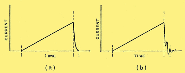
Fig. 3. A good practical saw-tooth wave is shown at (a); the stroke is linear, but the flyback is exponential. The waveform at (b) is met with sometimes and leads to the generation of very high peak voltages.
This is shown in Fig. 3, Where (a) depicts an exponential fly-back, and (b) shows the fly-back when the circuit is kicked into oscillation. To prevent this, the series combination of a resistance and a capacitor is often connected across the primary or secondary of the transformer. This resistance capacity circuit damps the coil, and the optimum conditions are obtained when it is adjusted so that the damping is just sufficient to prevent oscillation. Unfortunately, it tends to lengthen the fly-back time.
Reference has been made to the current changing by a certain amount in a given time, but no mention has been made of what makes it do so. The minimum time is governed by the time-constant of the deflection circuit that is, by L/R. If the grid volts of the output valve fall instantaneously to zero (or in practice if they fall more quickly than the anode current) the anode current change is only limited by the anode circuit, and it falls exponentially. This means that it takes infinite time to complete its change. In practice the next scan voltage on the grid comes along before the current has fallen completely and starts the next rise of current. The result is some loss of output. Suppose We arbitrarily say that in one-tenth the line time (10 μS) the current must fall to 1% of its initial value. Then approximately L/R = t/2.5 = 10-5/2.5 = 4 × 10⁻⁶. We have seen that in a typical case L = 0.164 H, hence R = 41 kΩ.
An output pentode has an AC resistance of the order of 20-60 kΩ and meets the case admirably, especially if its resistance is increased by the right sort of negative feed-back. There is one point to beware of if this is done, however, and especially if the resistance-capacity limiting circuit is not used. If the fly-back time of the saw-tooth voltage applied to the grid is more rapid than is necessary, or if it contains very rapid changes of voltage as when there is a superimposed oscillation, the anode current will be able to follow them, and the back EMF on the coil will be abnormally high. This is especially important in experimental work with saw-tooth oscillators, for when they are not working properly very peaky waveforms may be secured.
Arcs on the Fly-Back
The writer has experienced trouble of this kind. Curiously enough, the trouble is usually external to the valve. An occasional flash-over inside may occur in experimental work and apparently without doing any harm. He has had, however, a continuous arc develop between the sockets of the valveholder! Valves designed for magnetic time-base use now usually have a top-anode connection, but this is by no means essential it care is exercised in the choice of valveholder. As might be expected, quite a nasty shock can be obtained from the anode of the line output valve in spite of the supply of 300 Volts only.
The same troubles do not occur in the case of the frame time-base. It is usual to operate with about half the current and four times the inductance (the same amp-turns), but the fly-back time is roughly 100 times as long. The back EMF is thus only about one-fiftieth of that on the line valve, and no difficulty arises. Of course, one must always be on one's guard against faults which cause very peaky waveforms and so give rise to unusually high peak voltages.
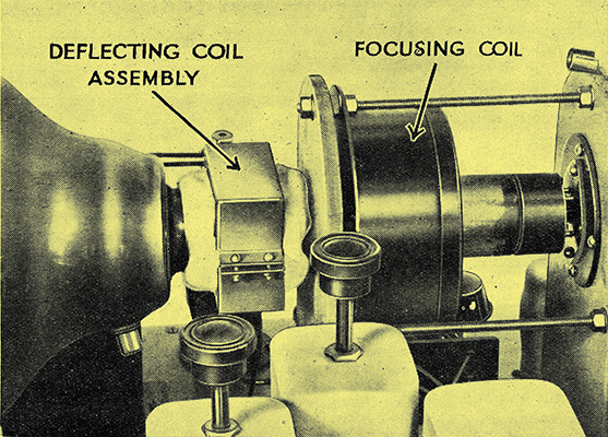
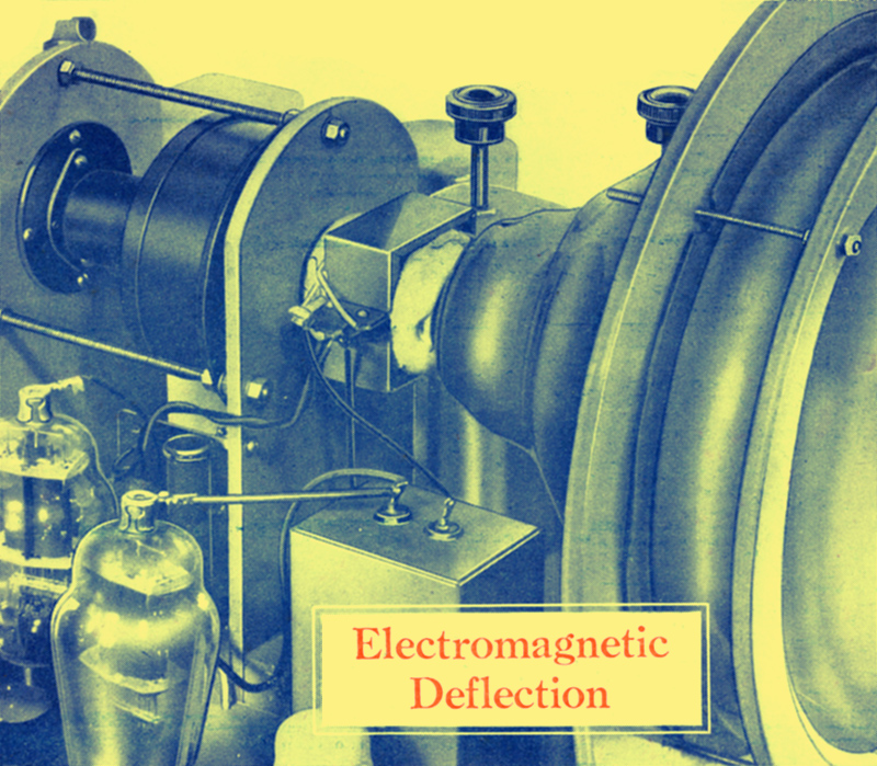
A view of a typical magnetic tube with the focusing and deflecting coils in place.
|