|
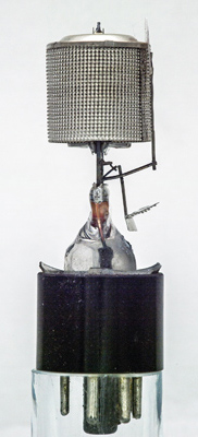 
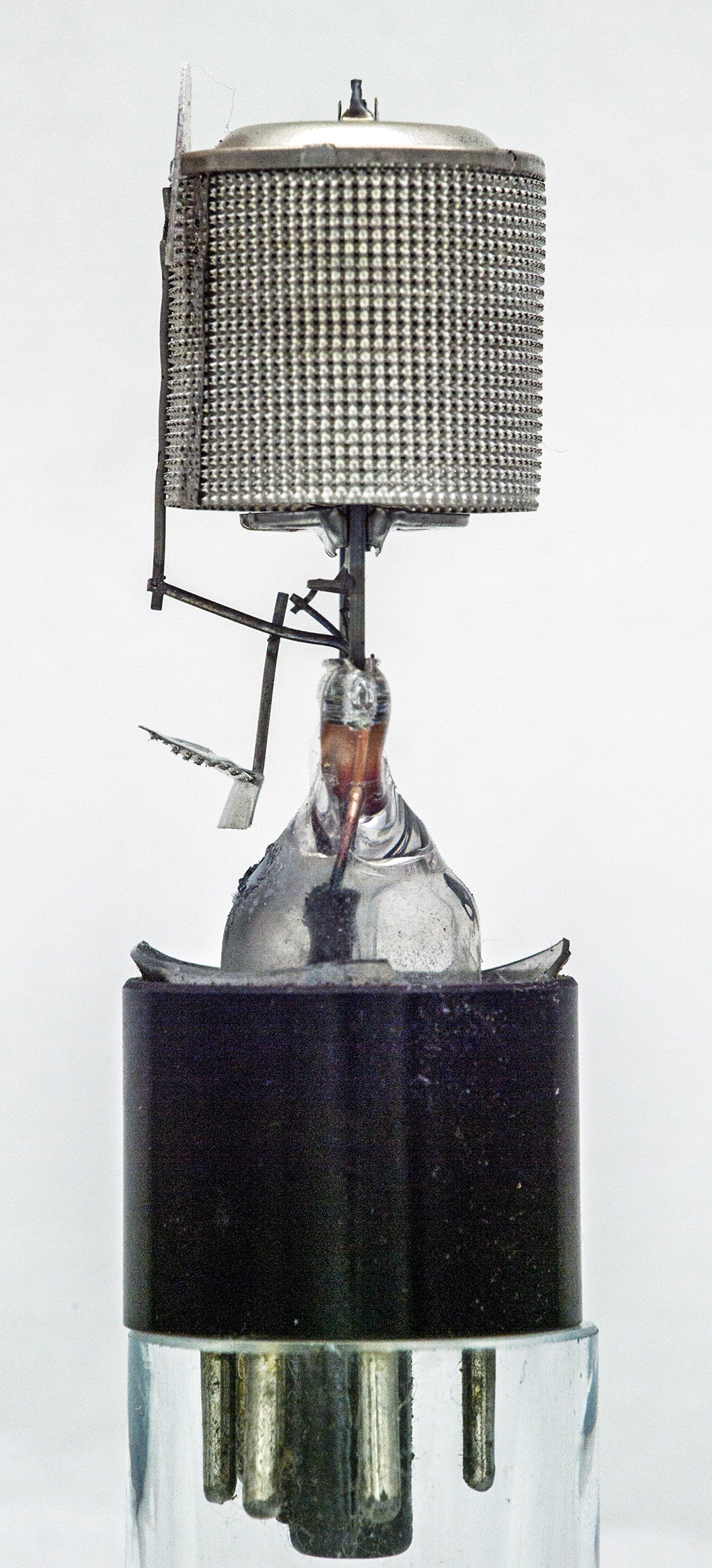
The 6C5G arrived with a broken envelope. On the right is a 6J7G Pentode.
This valve arrived with a broken envelope in a Brimar box. The glass that remained consisted of the plain dome and just the number 6 where the identification should be. By working out the pin connections and using the museum advanced search the number of possible valves became small. Working through the list the 6C5 triode was the one that fitted the data.
The 6C5G was not a common valve. The reason: it was superseded by the 6J5 which had slightly superior ratings and characteristics but was, for all practical purposes, a direct replacement.
The 6C5 was designed as an audio amplifier whereas the 6J5 was specified for both audio and RF. The 6C5G is a screened triode and there is some suggestion that it was produced quickly from the 6J7G design. Superficially the two look very similar. The 6J7G has a suppressor grid but the 6C5G does not. Both were designed for audio voltage amplification.
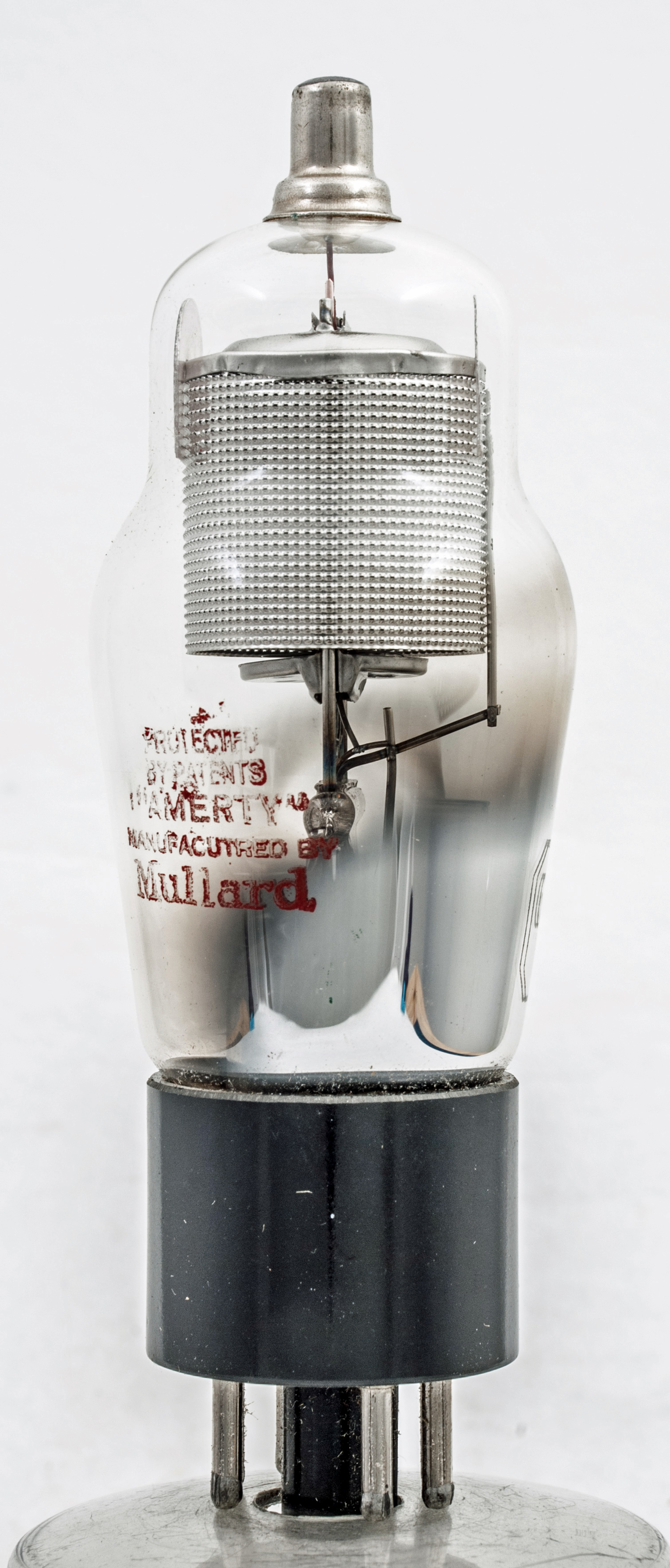
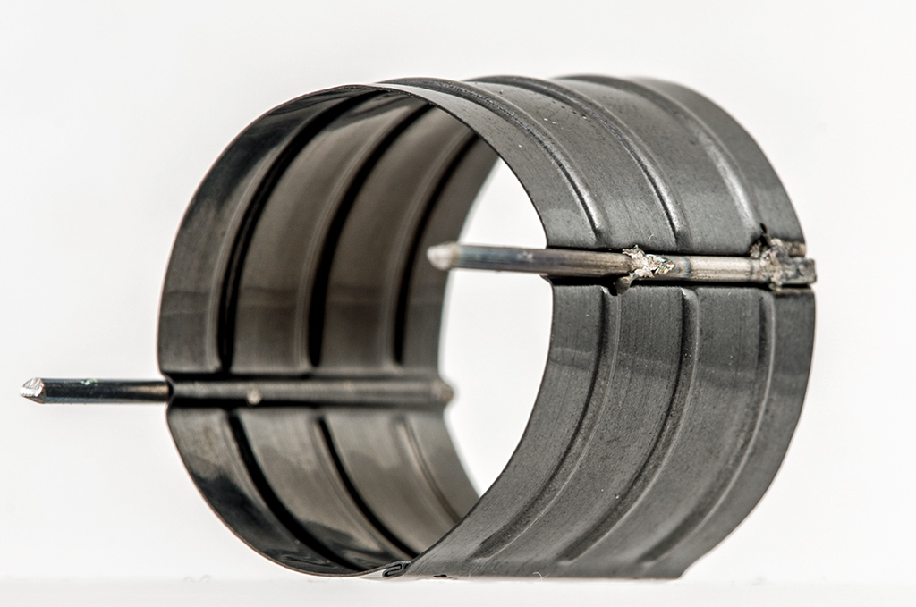
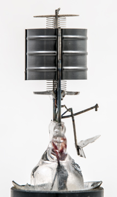
The 6C5G still intact.
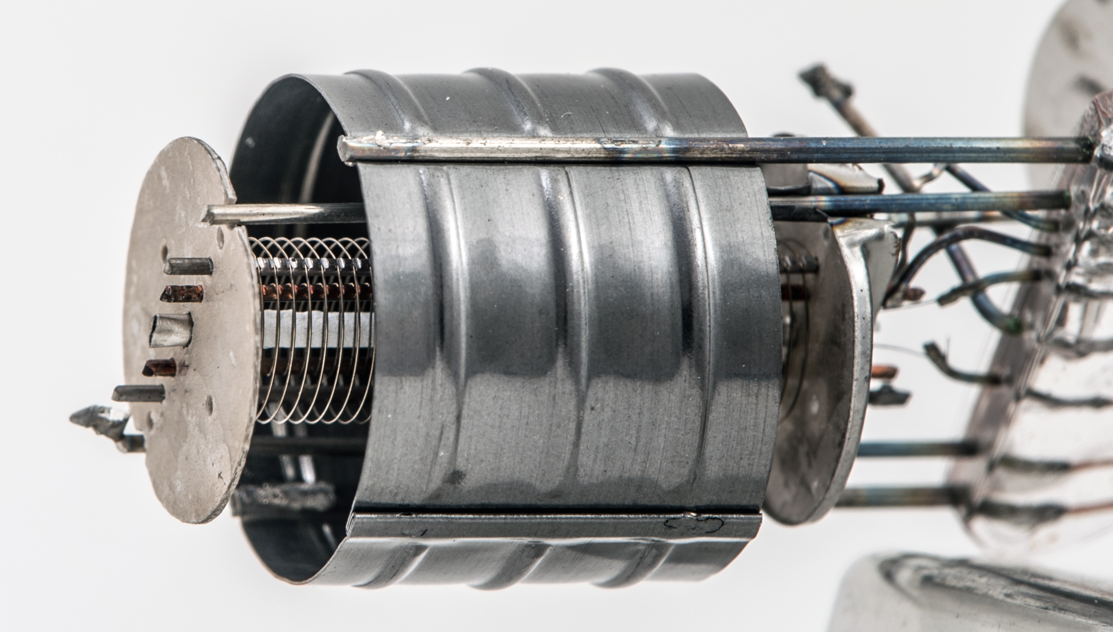
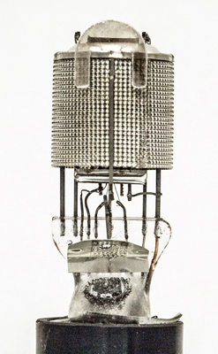
The outer screen is 24.4 mm in diameter and including the attached top screen is 25.40 mm tall. Note the connecting strap on the right between the outer grid and another electrode hidden under the screen.

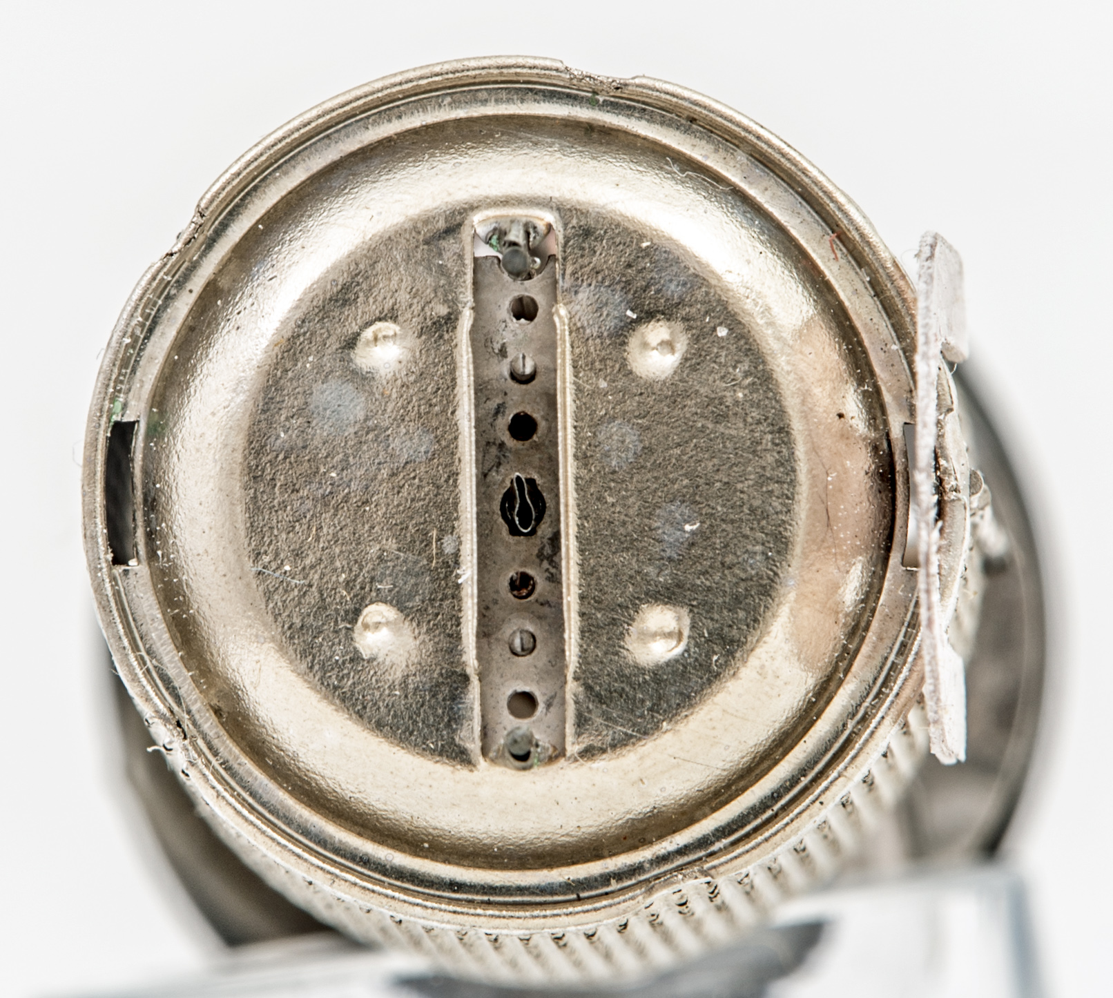
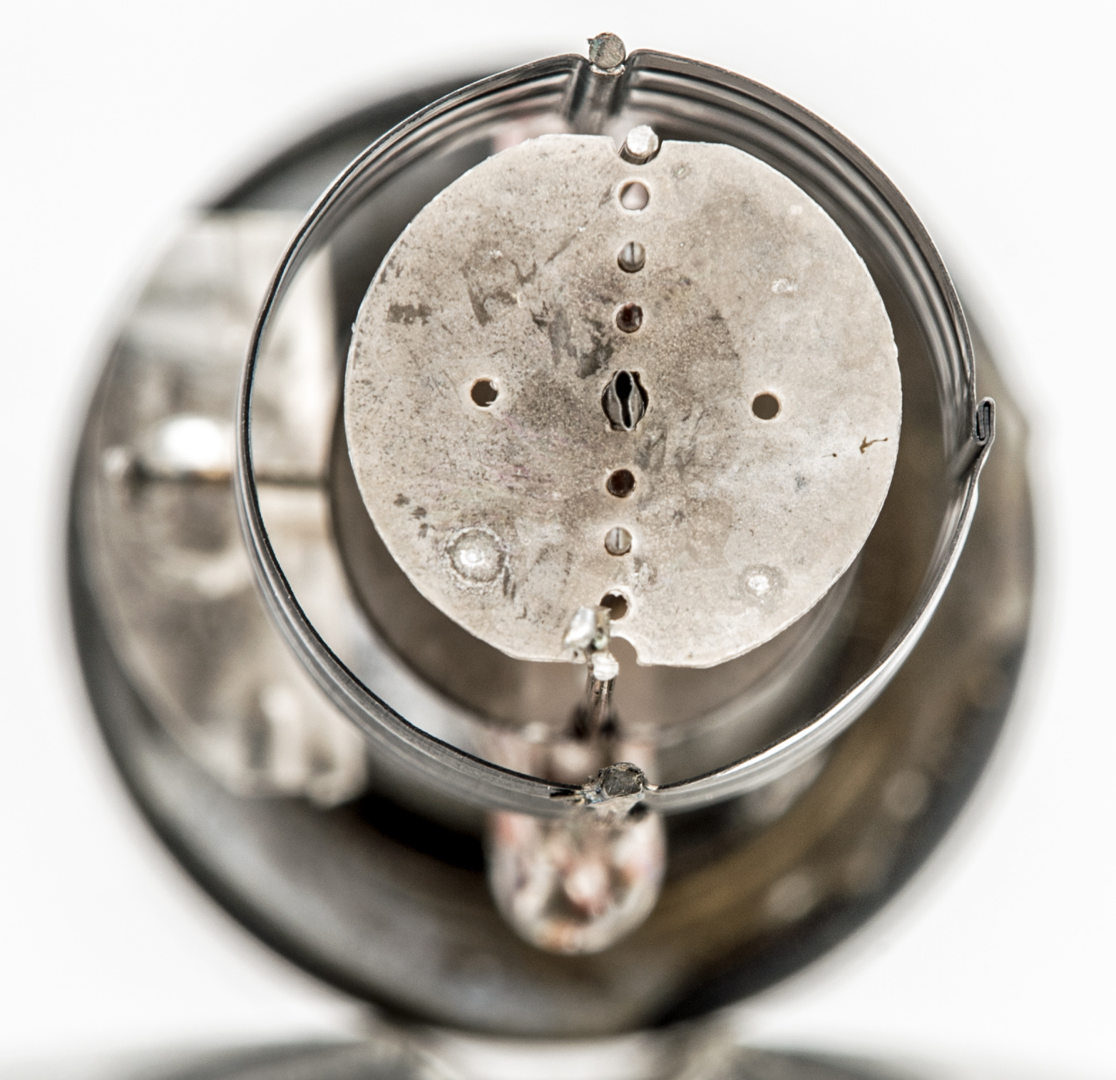
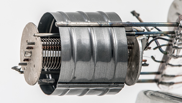
The screen seen from the top.
The central gap in the top of the screen shows the cathode tube and the pair of grid supports. The gap is 2 mm wide and 14 mm long.
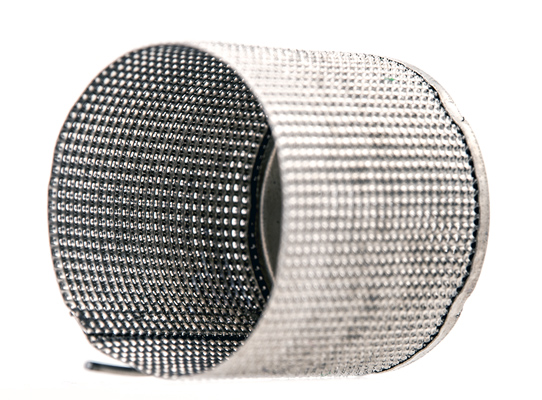
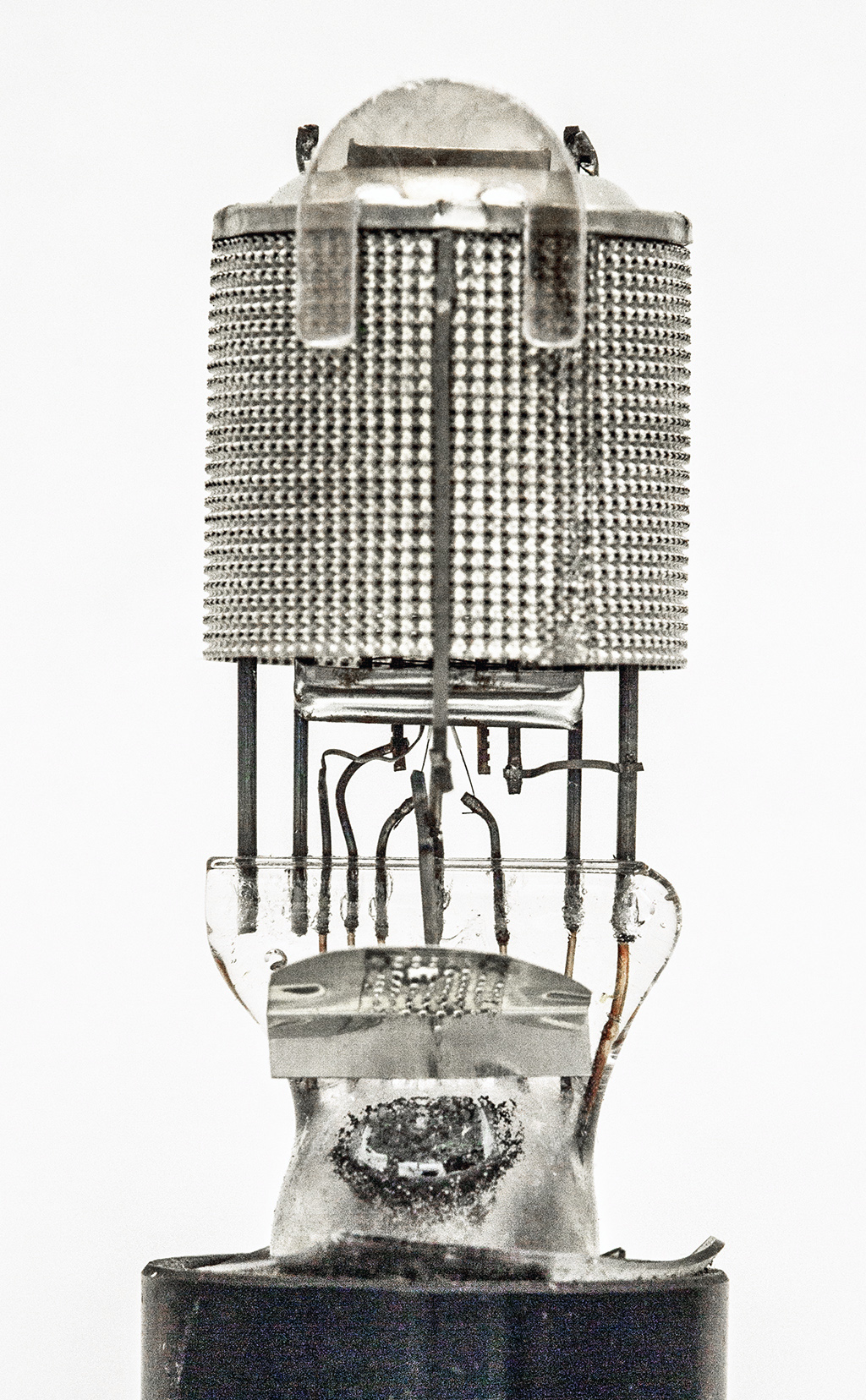
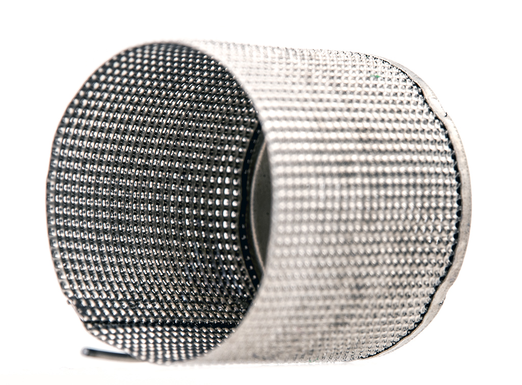
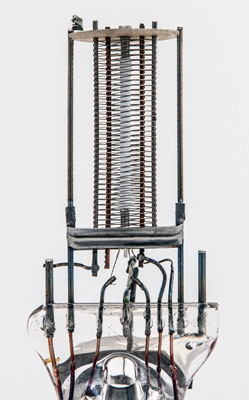
The perforated screen.
The screen was separated by cutting the side support, that also holds the getter holder but has no base connection, and then cutting the welds at the top of the two other support rods. These rods are embedded in the pinch but only the right hand rod has a connection to the base wires.
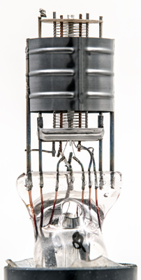
The anode.
With the screen removed the anode cylinder becomes visible. This thin nickel cylinder is 19 mm in diameter and 15.87 mm tall. The anode is blackened and ribbed for dimensional stability. The nickel sheet is 0.11 mm thick and the support rods are spot welded in two places each side.
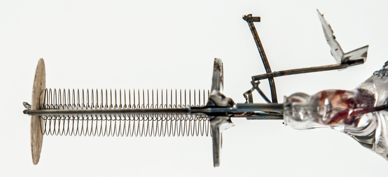
The screen side support and getter holder.
The outer grid supports are 8 mm apart and the grid is an ellipse that is 6 mm front to back normal to the grid axis.
Top mica disc.
The control grid is wound on copper supports. The outer grid has a close pitch and is connected to the anode.

Looking down onto the top mica disc.

The anode cylinder.
The anode has been formed in one piece with a folded seam. The pressing has also indented the sides to take the support rods.
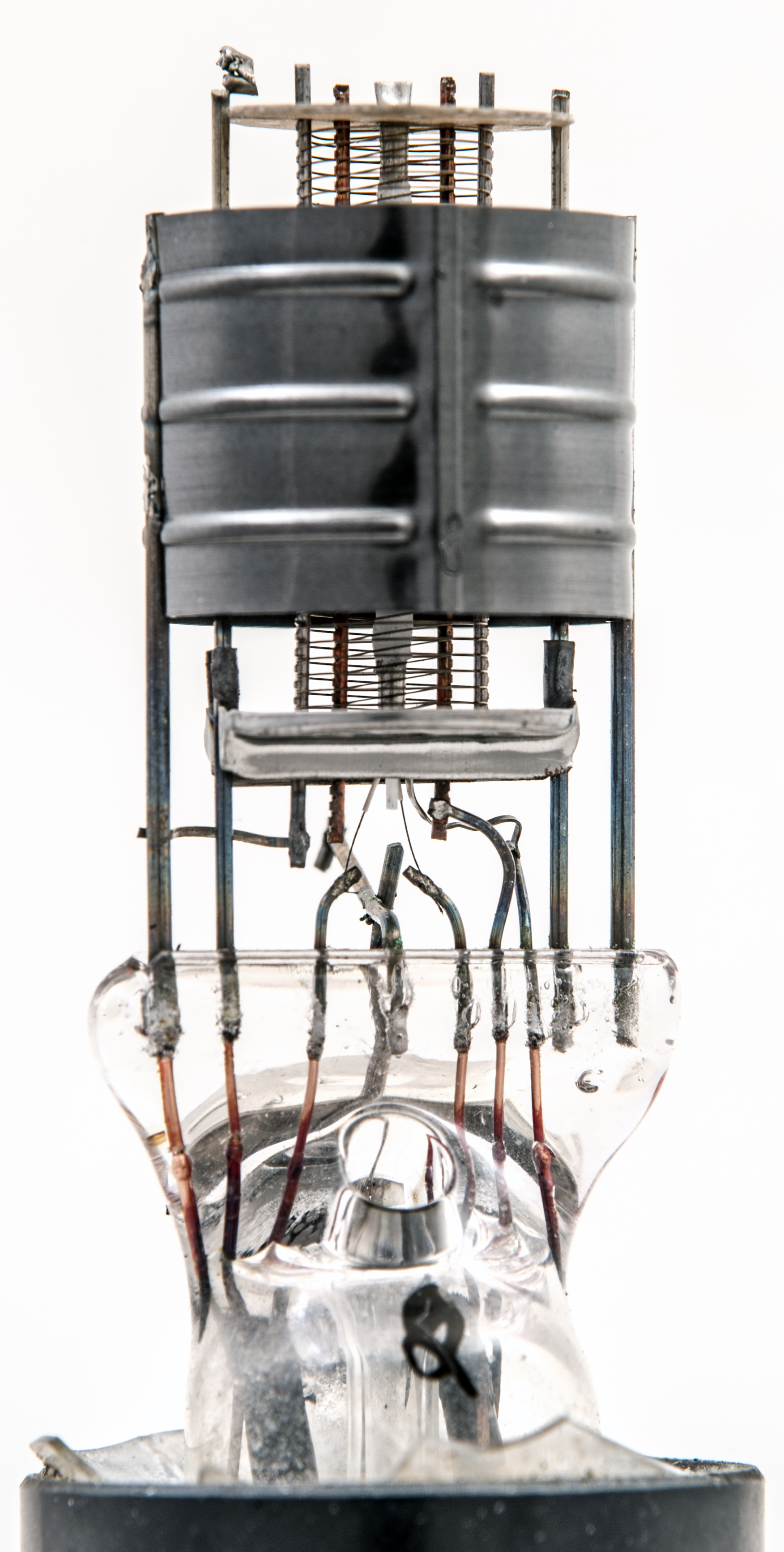
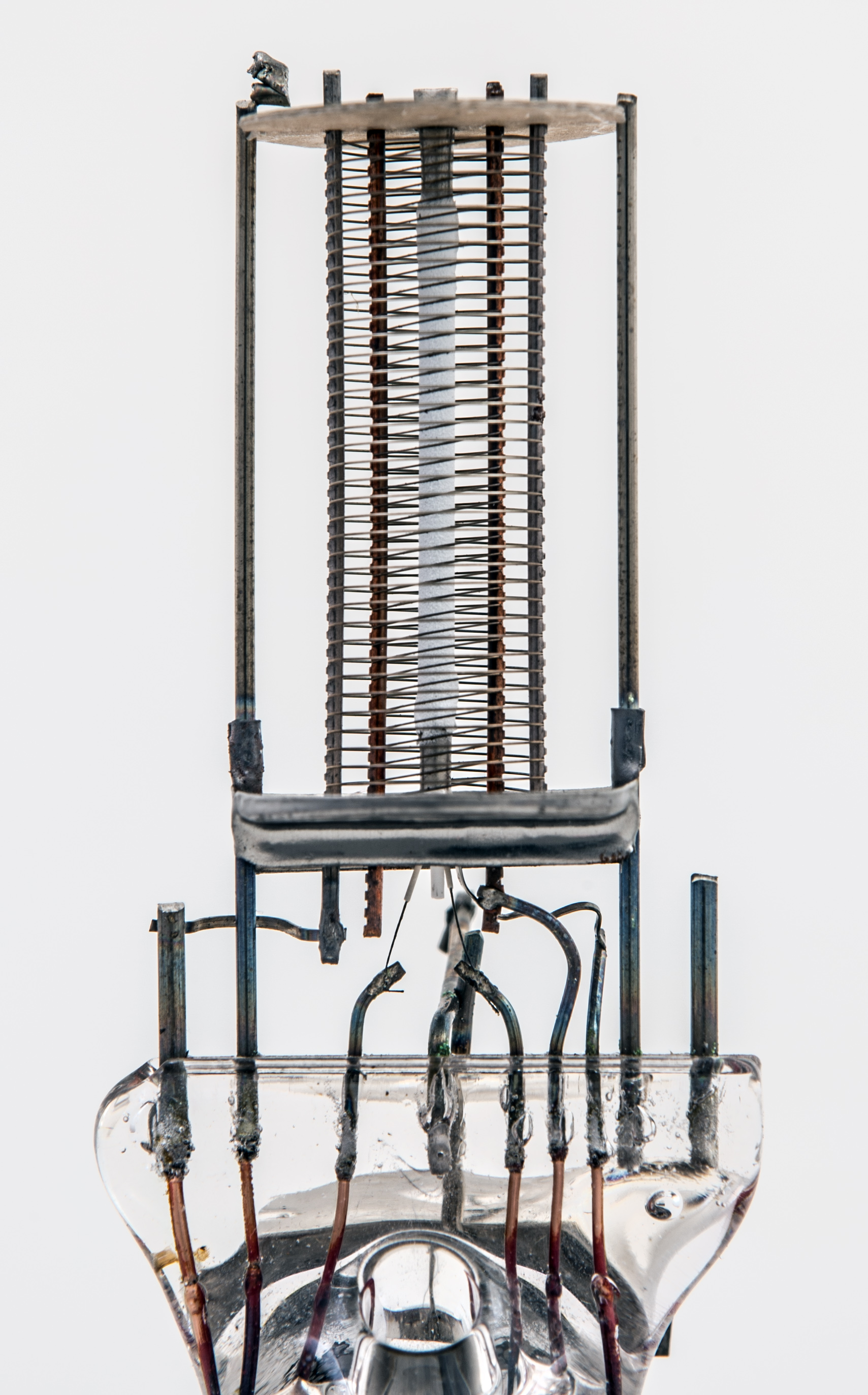
The grids and supports.
The outer rods are present to support the screen and are 14.36 mm apart as measured from outside edge to outside edge. The rods are 0.76 mm in diameter. The control grid supports are 4.82 mm apart. The cathode is a round tube with an oxide emissive surface coating. The cathode tube is 1.29 mm in diameter. The strap between the outer grid and the anode is clearly seen on the left above the pinch. The heater is a hairpin of insulated wire that is welded to the supports. Thus this wire cannot be tungsten.
Measuring from the full size image gives the control grid pitch as 0.582 mm. The outer grid looks to have the same pitch.
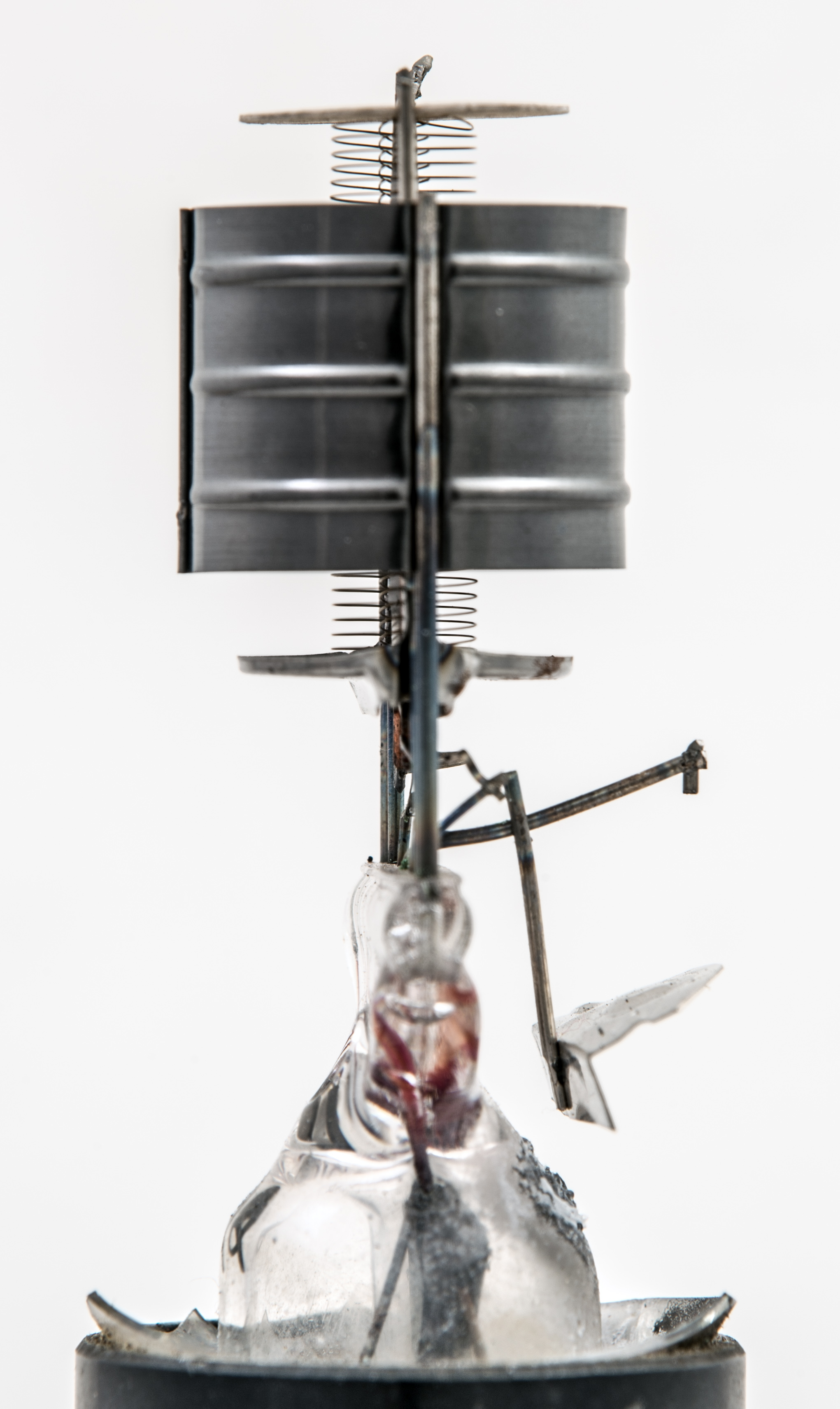
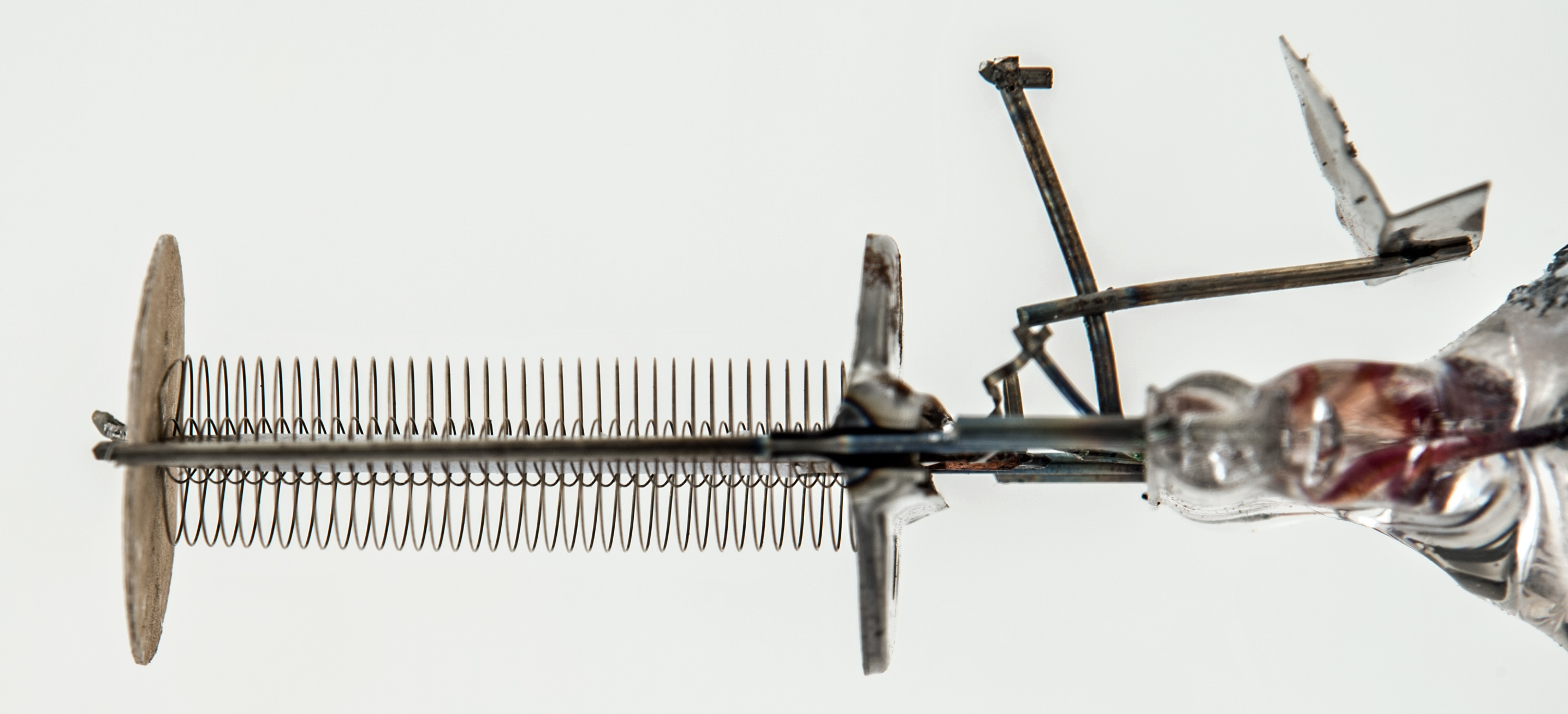
Looking along the grid axis.
Measuring from the image the outer grid is 6.4 mm across and has a pitch of 0.64 mm. The control grid is 2.23 mm across with a pitch of 0.625 mm.
The measurements taken from the photographs will be subject to some error but the control grid pitch looks to be 0.6 mm.
The reason for a second grid connected to the anode is not known.
|