|
Describing an arrangement in which changes of potential that would normally produce hum are balanced out by the action of a triode valve. The method is largely independent of frequency.
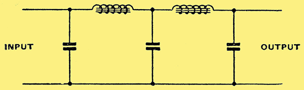
Fig. 1. Conventional two-stage smoothing circuit as used with high-quality amplifiers of moderate gain.
It is now almost universal to employ a combination of chokes and capacitors for smoothing - to use, in fact, a form of low pass filter. Chokes in series with the HT supply and capacitors shunted across it form a very satisfactory filter, for they provide adequate smoothing for most purposes and are reasonably cheap. Even for high-quality apparatus two chokes and three capacitors arranged as in Fig. 1 prove adequate with a normal AF amplifier of only moderate gain.
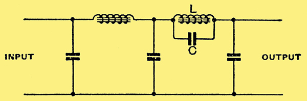
Fig. 2. The artifice of tuning one of the smoothing chokes to resonate at the predominant hum frequency does not always work out satisfactorily in practice.
It has often been suggested in the past that the smoothing could be greatly increased by tuning one of the chokes by means of a shunt capacitor C (Fig. 2). The greater smoothing would then enable the filter to be used with a higher gain amplifier, or else it would permit a reduction in the size of the chokes and capacitors.
Hum Frequency
In practice, however, this scheme is not very useful. While it can occasionally be adopted, it fails for general use because mains hum does not consist of a single frequency. With the usual full-wave rectification the ripple has a principle frequency of twice the mains frequency, or 100 Hz in most cases. There are appreciable components of higher frequency, however, which can be important since the ear is more sensitive to them.
By adjusting C in Fig. 2 so that LC resonates at 100 Hz, a very large reduction of hum of this frequency can be secured, but the presence of C causes an increase in hum of other higher frequencies. If the hum in the output of an amplifier is measured by a meter which does not discriminate between different frequencies, it is quite easy to adjust C so that a big reduction of hum is indicated. When a listening test is adopted, however, it is not uncommon to find that the audible hum is greater than before, but of higher frequency. A low-pitched hum has been turned into a high-pitched one of apparently greater intensity.
The total hum has been decreased, as indicated by the meter, but the high-pitched hum has been increased, and as the ear and loud speaker are more sensitive to it the net result is a deterioration of performance. Because of this the circuit is but little used, and it is usual to adopt the arrangement of Fig. 1. In the case of very high gain amplifiers, such as microphone amplifiers, it is not always easy to get sufficient smoothing. In such cases considerable interest attaches to a special balancing circuit which is largely independent of frequency and which will theoretically reduce hum to zero.
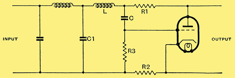
Fig. 3. The balancing circuit of which the operation is described in this article.
The arrangement is shown in Fig. 3 and it will be seen that a valve, a capacitor, and three resistances are used to replace the output capacitor of the filter. [★] Electronics, June 1937.
Assuming linear valve characteristics and that the reactance of C is very small compared with the resistance of R3 at the lowest important frequency, the hum output is zero when the circuit is correctly balanced.
Valve Action
What happens is this. When the ripple causes a momentary rise of anode voltage this change of voltage is also communicated to the grid of the valve through C, causing the grid to become less negative. This increases the anode current and the anode voltage falls owing to the increase of current through the resistances. When the circuit is balanced the fall of anode voltage due to the change of grid potential is just equal to the rise due to the ripple on the supply and no change of anode voltage results. In other words, the change has been completely smoothed out.
The condition for balance is that the sum of R1 and R2 Ohms should equal the reciprocal of the mutual conductance of the valve in amperes per volt (R1 × R2 = 1/g). R2 is to provide bias for the valve and its value depends on the bias needed and the total current taken from the supply.
Suppose the total current, including that taken by the smoothing valve, is 50 mA. and 3 Volts bias is needed, while the valve has a mutual conductance of 3 mA/V. Then R2 = 3/0.05 = 60 Ω, R1 + R2 = 1,000/3 = 333 Ω, and R1 = 333 - 60 = 273 Ω. The total resistance of the HT supply is increased by R1 + R2 and in this case there will be a loss of voltage of 333 × 0.05 = 16.65 Volts.
In practice R1 should be made variable so that an exact balance can be secured, and to suit the above example a component with a maximum value of some 500 - 600 Ω would be suitable. It is also necessary to take care that the valve is not overloaded by the ripple, otherwise it will introduce harmonics of the predominant ripple frequency and be open to the same drawbacks as the circuit of Fig. 2. There is probably little risk of this if a stage of normal smoothing is used preceding it, as shown in Fig. 3.
The values of C and R3 are not critical. R3 should be as high as possible and 0.5 MΩ is a suitable value; C must be large enough in relation to R3 to cause negligible phase shift at the lowest hum frequency. A value of 1 μF is quite good.
The choice of valve is not difficult. It should have a high mutual conductance in order to keep R1 + R2 low, a low anode current for economy, and a long grid base so that it can handle a large ripple voltage without distortion. Some of these requirements are conflicting, but if care is taken not to apply too much ripple to the valve a small AF triode is suitable. A valve of the MH4 class will usually be satisfactory.
Another advantage of the system is that the output impedance is resistive and nearly equal to 1/g; when g= 3 mA/V the impedance is about 333 Ω This holds at all frequencies for which the reactance of C is very small compared with R3 and provided that the shunting effect of the preceding components, such as L and C1, is negligible. In practice, this usually means that the output impedance is substantially constant for frequencies higher than a certain low frequency which is normally well below the mains frequency.
The output impedance is not maintained constant down to zero frequency, so that for television purposes the circuit offers little advantage in this respect over the conventional one. It can give better smoothing, however. Its greatest application probably lies in microphone amplifiers and laboratory equipment where the attainment of a minimum of hum is an essential requirement.
|