|
Which is the best arrangement.
The magazine cover picture.
It has been said that reaction comes nearer than anything else in radio to giving something for nothing. As economy is vital under wartime conditions, it is worth while examining the possibilities of reaction, particularly for short-wave work, in the light of modern knowledge. In the present article circuit arrangement receives most attention, but subsequent articles will deal with valve-operating conditions and similar related matters.
The use of reaction has become much less general in recent years, and now the majority of receivers do not include it at all. This is largely because improvements in valves and circuit design have made it easy to get the required sensitivity without it. In spite of this, reaction still has its uses, especially in short-wave equipment. Short-Wave sets can be divided into four groups:
- the small straight set;
- the SW band of a broadcast set;
- the small communication set;
- the large communication set.
Sets of the second and fourth groups rarely make any deliberate use of reaction, but those in the first category rely on it very largely for their sensitivity and selectivity. The third group is a newcomer, and quite a small one up to the present. The sets in it are designed with the aim of approaching the performance of the large communication sets with a simpler circuit and fewer valves. Reaction is employed more to increase selectivity than sensitivity, and it is used in a moderate degree only; it is not pushed to the edge of oscillation as is essential in the case of the small straight sets of group 1.
Reaction is so old and so well known that it might be thought that little fresh could be said about it. This is far from being the case, however, for so much that has been said about it in the past has been based upon uncontrolled experiment and comparatively little upon theoretical analysis checked by controlled experiment. Because of this, general statements must be treated with caution.
It has become accepted that one of the best methods of reaction control is by variation of screen voltage of a tetrode or pentode valve. This is now probably the commonest method of control in short-wave apparatus because it has much less effect on the tuning than many other possible arrangements. It anyone were to conclude from this that it is always the best arrangement, however, he would be sadly disappointed. It is easy to show theoretically that while it is very good in some circumstances it is very bad in others. There are three main requirements of a good reacting system: variation in the setting of the reaction control should not affect tuning, the valve should go smoothly into oscillation, and there should be no backlash. All three are important when critical reaction is used, but when only a moderate degree is employed the attainment of smooth oscillation is less important. This is because the valve will never be intentionally worked close to the oscillation point. For the same reason the avoidance of backlash is less important; it is still very desirable, however. When backlash is present it is quite possible for a strong signal or a peak of interference to start the valve oscillating, and once started it will not stop until the reaction control is slackened off.
Effect of Valve and Circuit
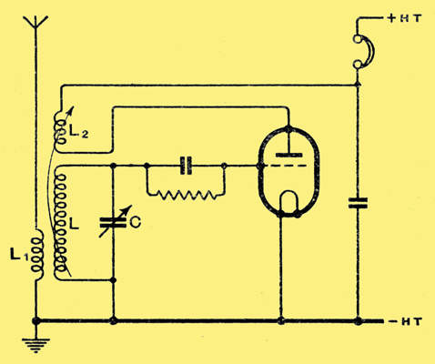
Fig. 1. This diagram shows the classical swinging-coil reaction circuit.
The variations of tuning experienced depend chiefly upon the circuit adopted, but the smoothness of oscillation and backlash depend upon the valve used and the voltages applied to it. The effects are not completely separate, and it would not be true to say that smoothness and backlash depend only on the valve and voltages; the circuit does have an effect, and one which it is sometimes hard to disentangle.
The classical reaction circuit shown in Fig. 1 was in common use in the very early days of broadcasting. The tuned circuit LC is coupled by L1 to the aerial, and reaction is obtained with the aid of L2. Reaction is controlled by varying the physical distance between, or the angle between, L and L2.
The great drawback to the arrangement is the considerable variation of tuning experienced with changes in the reaction coupling. Apart altogether from secondary electrical effects, the mechanical movement of the coils necessarily changes the circuit capacity and so alters the tuning.
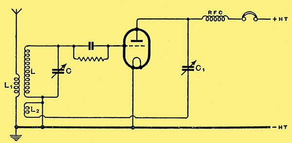
Fig. 2. The common capacitor controlled or Reinartz reaction system. This is still probably the most widely used of any.
To overcome this it became customary to adopt a fixed coupling between the coils With a capacity control of reaction. There are many possible variations of this scheme, but the commonest is that shown in Fig. 2, which is still in use today. Sometimes the reaction capacitor C1 is placed on the earthy side of the coil L2, and this is less likely to give hand-capacity effects. Provided that the capacity between L and L2 themselves is small, however this make little difference, and so one can be guided by convenience.
This circuit is a considerable improvement, but is by no means perfect. At low operating frequencies when the anode-cathode valve capacity can be considered negligible, L2, C1, and the valve resistance can be considered as a series-tuned circuit coupled to LC. Changing C1 alters the resonance frequency of this circuit and so alters the tuning of LC, since the two circuits are coupled together. Owing to the very high circuit resistance, however, this effect is small.
At high operating frequencies the anode-cathode capacity plays an important part. Ignoring the valve resistance for the moment, it comes in series with C1 across L2. The reaction circuit then becomes a tuned circuit of only moderate resistance, and although its resonance frequency may be widely different from that of LC, an alteration in the capacity is reflected into the circuit LC. The finite value of valve resistance modifies things somewhat; but the general effects remain. At very high frequencies this circuit fails because it is very difficult to secure a sufficiently large mutual inductance between L and L2 to secure oscillation Without making L2 so large that it resonates with the various circuit capacities at or below the resonance frequency of LC. With ordinary valves the upper-frequency limit for this circuit is usually about 60 MHz as an oscillator, and it is often difficult to make it work above 40 MHz. For reaction purposes the latter frequency should normally be taken as the upper limit.
For Ultra-Short Waves
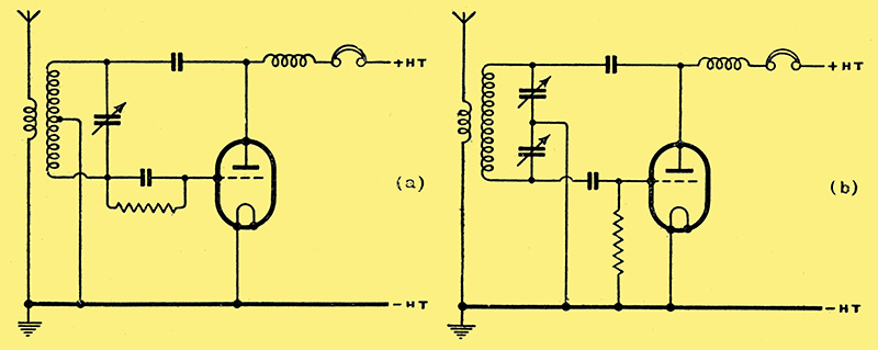
Fig. 3. The true Hartley and Colpitts circuits are shown here at (a)and (b) respectively.
For high-frequency work generally it is more usual to employ some form of the Hartley or Colpitts circuits shown at (a) and (b) respectively in Fig. 3. These have many variations, especially in the method of controlling regeneration. Probably the most widely used is the Hartley modification of Fig. 4.
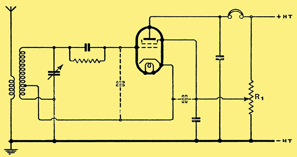
Fig. 4. This modified form of the Hartley circuit is commonly used with an indirectly-heated valve. It permits one side of the tuning capacitor to be earthed. Reaction is controlled by varying the screen voltage by means of R1.
A screen-grid or pentode valve is used and the cathode is tapped up the coil so that the valve oscillates with normal screen volts; regeneration is controlled by varying the screen voltage by R1.
This arrangement can be made very satisfactory the Hartley oscillator is always more liable to trouble than the Colpitts. This is because it is impossible to prevent its being a Colpitts oscillator as well as a Hartley! If the important valve capacities are drawn in on Fig. 4 (dotted) it will be seen that the grid-cathode and screen-cathode capacities form the split condenser of the Colpitt's circuit. Provided a high impedance path to RF and low impedance to DC were maintained between cathode and earth, the circuit would still work with the tap on the coil removed it would then actually be a Colpitts circuit.
Because it is really two circuits in one the Hartley circuit is sometimes troublesome; it may try to work in one mode at one end of the tuning range and in the other mode at the other end. Naturally all sorts of peculiar effects take place in the region where the change over occurs. This particular trouble does not occur with the Colpitts oscillator, and it is often simpler because the coil does not need tapping. An analysis of its conditions is rather more easily carried out than in the case of some other circuits. and it is then easy to show that some of the usual arrangements of controlling regeneration in Colpitts receiver circuits are not the best that can be devised.
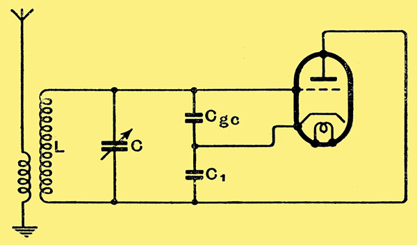
Fig. 5. This is the basic circuit of the Colpitts oscillator when the valve inter-electrode capacities are used to provide the tapping point on the tuned circuit.
The basic circuit is shown in Fig. 5, Where the detector arrangements, HT supply, and DC circuits have been omitted. It can be shown that the part to the right of LC behaves as a capacity Cin in parallel with a resistance Rin. The resistance can be positive or negative. If it is the latter regeneration occurs, and oscillation commences when the negative resistance is numerically less than the dynamic resistance of the circuit LC.
If we use this arrangement as a reacting system it is necessary to be able to vary Rin at will, and it is necessary that changes of Rin should affect the input capacity Cin as little as possible. The problem of design consists of choosing that form of control which most nearly meets this condition.
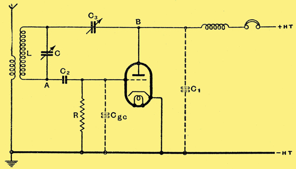
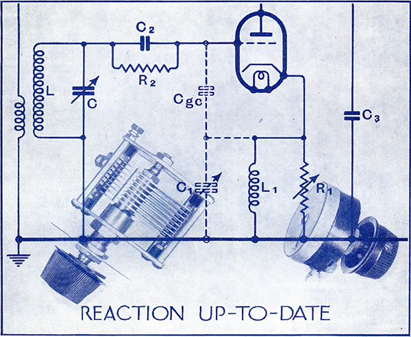
Fig. 6. A commonly used Colpitts circuit in which regeneration is controlled by C3.
Now when this Colpittbs circuit is used for reacting purposes it is usually arranged in the form shown in. Fig. 6, where the grid-cathode capacity Cgc and the anode-cathode plus stray capacities C1 form the necessary capacity for the tuned circuit LC. The grid capacitor C2 is large enough in relation to these others to have a negligible effect. C3 is the reaction control.
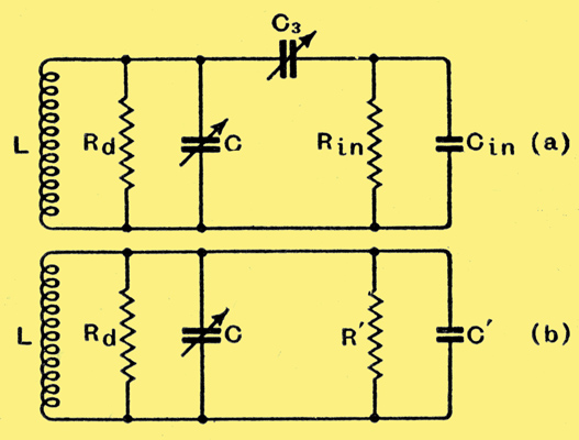
Fig. 7. The equivalent circuit of Fig. 6 is shown at (a); it can be further reduced to (b), as explained in the text.
Measured between the points AB the valve will behave as a capacity Cin in parallel with a negative resistance Rin. The equivalent circuit is thus of the form shown in Fig. 7 (a), and this can be still further reduced to Fig. 7(b), and it is clear that varying C3 changes both R' and C'.
Suppose that at 30 MHz (10 metres) Rin is -2,800 Ω and Cin is 3.9 μμF. These are also approximately the values of R' and C' when C3 is large for full regeneration. Now let us reduce C3, say to 3.9 μμF. Then R' becomes -11,850 Ω and C' becomes 2.16 μ&mu:F. When C3 becomes zero R' is infinite and C' is zero.
To vary R' from -2,800 Ω to infinity involves a change of C' from 3.9 μμF to zero. In practice a change of resistance of 11,850 - 2,800 = 9,050 Ω involves a change of capacity of 3.9 - 2.16 = 1.74 μμF. It the total tuning capacity is 25 μμF, as it may well be, this means a change of 6.96%, which will entail a change of resonance frequency of roughly 3.4% or about 1 MHz!
One method of overcoming the difficulty is to make C3 fixed and to control regeneration by a variable resistance shunted across C. This means using a fixed value of negative resistance and a variable positive resistance in the tuned circuit instead of the more usual course of keeping the positive resistance fixed and varying the negative resistance. A resistance shunted across C would be a perfect control since it would cause no change of tuning, It is, however, very doubtful whether it would be satisfactory in practice, because of the difficulty of obtaining a suitable variable resistance. The internal capacity would have to be constant or negligible at all resistance values.
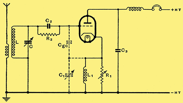
Fig. 8. This version of the Colpitts circuit is particularly convenient since the tuning capacitor can be earthed. Regeneration can be controlled by C1 or R1; it is shown in the text that C1 should be used at low frequencies and R1 at high frequencies.
If we make C3 fixed or omit it, we can control regeneration by varying C1 or Cgc by varying a resistance in parallel with C1 or by altering the valve 'constants' through changing the voltages applied to it. Let us redraw the circuit in the form of Fig. 8. Here C2 and R2 are the grid leak and capacitor for grid detection and if C2 is large enough they play no direct part in regeneration. C3 is the anode circuit bypass capacitor, assumed to have negligible reactance at the operating frequency. The coil L1 in the cathode circuit is assumed to have such a large reactance that it can be ignored; its purpose is merely to provide a low resistance direct current path.
The essential factors governing the input impedance of the valve are Cgc, C1, R, and g, where g is the mutual conductance of the valve and R = R1 Ra/ (R1 + Ra) ; that is, R1 in parallel with the anode AC resistance of the valve. This ignores the grid-cathode resistance, which is likely to be fairly high when R2 is large.
The input capacity Cin and input resistance Rin depend on all four quantities, so that, whichever is varied to change Rin, then Cin is necessarily altered also. There are, however, two limiting cases. When (1 + gR) / ω2C1 Cgc R2 << (1 + C1/Cgc) and (1 + gR)2 / ω2 Cgc2 R2 << (1 + C1 / Cgc)2 then Cin ≈ C1 / (1 + C1 / Cgc). Obviously, neither C1 nor Cgc can be used as a reaction control; but if either R or g is varied Cin is nearly constant.
The above conditions are, in practice, most nearly met at high frequencies and we find that the correct reaction control is then R or g. R can be varied by using a variable resistance for R1; g can be altered by changing the anode (or grid) voltage of the valve. This will also alter Ra and hence R. This voltage control has for long been used as a regeneration control in SW equipment. Found originally by experiment, it has decided theoretical justification.
There is, however, another extreme condition, when (1 + gR) / ω2 C1 Cgc R2 >> (1 + C1 / Cgc) and (1 + gR) / ω2 >> (1 + C1 / Cgc)2. The input capacity Cin ≈ Cgc / (1 + gR). Under these conditions Cin is no longer dependent on C1 or Cgc, but is greatly dependent on both g and R. When these conditions hold, therefore, it is definitely wrong to control regeneration by varying R1 or the voltages applied to the valve. The correct thing to do is to vary C1 or Cgc and the former is usually the more convenient. These conditions are most nearly fulfilled at low and moderate radio frequencies.
In order to obtain the minimum change of input capacity reaction should be controlled by g or R at high frequencies and by C1 or Cgc at low or moderate frequencies. In practice, the former condition applies for general short-wave reception and the latter at frequencies below some 500 kHz.
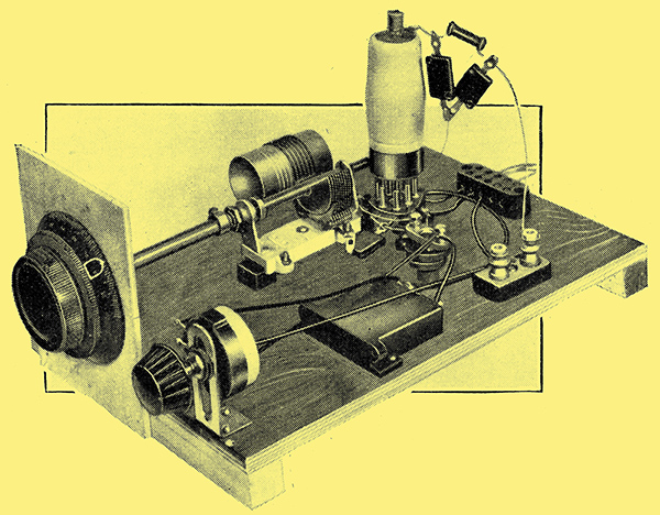
Experimental receiver for testing the reaction circuits discussed.
|