|
In this article the former Chief Engineer of the BBC explains the technical means of putting into effect a project in which he has long been interested.
One must assume that the object of a broadcasting service is to interest - which is also amuse - the listener. But there is no such person as the listener; the public is composed of all sorts of listeners with varying tastes and prejudices, so, in order to amuse 'all of the people all of the time', broadcasting must cater for widely different tastes. It can only do this by simultaneously offering the listening public a large number of programmes to choose between. The listener should be able to listen 'a la carte'; at present the poor chap has to 'take the dinner'.
It is not possible to give a multi-programme service by radio because of the limitation of channels. True, one can 'hear' lots of stations, but they all send the same type of programme. There is no continuous service of jazz, talk, symphony, light music, plays or whatever there could be if there were enough channels.
If wires rather than wireless waves were used to link the listener to the programme source, theoretically, any number of channels are available for the diffusion of any number of programmes. Obviously, carrier transmission would be used; transmitters would send their output into the network. Receivers, physically connected to the network, would be tuned to this programme or that. It is a radio system which does not radiate? Therefore, the carrier frequency separation can be ideal for high-fidelity reproduction, the signals strong enough to overcome any noise, and the receiver robust and simple.
Existing Wire Networks, or . . .?
A national service of wire broadcasting demands the existence of a conducting network interconnecting every house in the kingdom. This network could be constructed anew to form the basis of a 'general communication' system, or the existing telephone and 'electric mains' networks could be employed by superimposing carrier currents.
Sooner or later - later, if we go on being stupid - a new network will be constructed. It is within the bounds of possibility that this could be designed to diffuse a large number of sound and vision programmes as well as being used for the private telephone system. The super-imposition of facsimile would print newspapers and periodicals in peoples homes and give a written message and telegraph service - all on a pair of wires! At present the idea is not feasible - 'it would cost too much', - that is to say, it would cost three weeks present war expenditure and earn a turnover around the hundred-million mark.
A start could be made by using existing networks to transmit, say, six sound broadcasting programmes. My friend and colleague, R E H Carpenter, and I started, in about 1930, to see if the electric mains network could be used to distribute a broadcasting service. Obviously, the idea was based on using carrier currents which, of much higher frequency than the mains currents, could be injected into and picked off the network by the use of very simple filters, rejecting the 50 Hz currents and passing the high-frequency currents.
The mains network has an intrinsic advantage in that in this country it reaches five households where the telephone is only installed in one. Otherwise, I should guess that the telephone wire broadcasting system presents fewer problems. [★] Technical details of the Post Office project for broadcast distribution over the telephone system were published in The Wireless World, September, 1940. The attenuation of the telephone pairs is less than that of a buried mains cable, and each telephone pair can be ideally terminated. The mains networks are interconnected in a complex manner, and have variable terminations. Nevertheless, if these problems of adapting the mains network, formidable as they appeared to us when we started, can be solved, the paramount advantage that the mains reach far more households remains.
The Transmission System
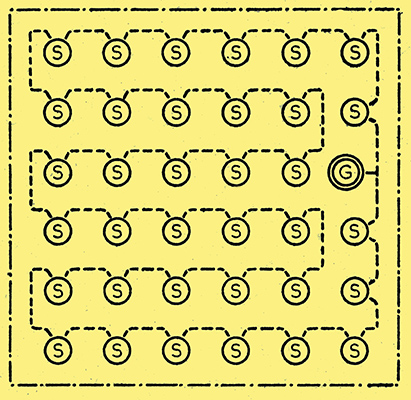
Fig. 1. Diagrammatic representation of layout of sub-stations and ring main.
We think we have solved these problems. I propose to give a very general description of the system which has been perfected for transmitting broadcasting programmes over the electric mains. The system is applicable to the great majority of systems typically in use in this country for urban and suburban domestic electricity supply.
Before describing the broadcasting system it is necessary to explain the fundamentals of a typical supply system.This will be easier by reference to the diagram of Fig. 1. This is formalised. The dash-dot line represents the boundaries of a supply area, London borough, a provincial town, or what would you? A dotted line represents a so-called 'ring main', which, buried underground, weaves its way over the area, touching sub-stations S as it goes. It is energised from a source of power - the grid or a generating station - at G. The ring main carries power at voltages ranging between 6 and 33 kilovolts, and distribution is three phase.
Each sub-station contains a transformer, its primary energised from the ring main, the secondaries being.connected to the street cables which take the supply from the sub-stations to the consumers houses.
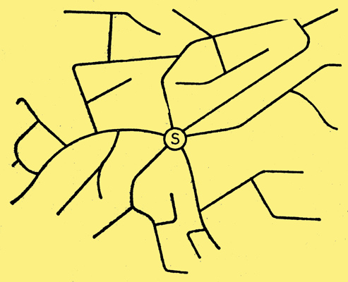
Fig. 2. Hypothetical layout of street cables.
The street cables, as shown in Fig. 2, run out from the sub-station, under and along the streets. The cables, as is seen from this typical picture, are interconnected. The shape of the network is determined purely by the run of the streets. Branch feeders, not shown, run from the street cables into the houses lining the streets.
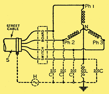
Fig. 3. Method of injecting radio-frequency currents into the supply network at a sub-station.
Fig. 3 shows the schematic connections of a sub-station. The power distribution system is shown in full lines, the added connections, necessary for injecting the carrier currents into the street cables, in dotted lines. Only one outgoing cable and the secondary windings of only one power transformer is shown, it being understood that there may be many street cables and, several transformers. The primary of each transformer is energised from the higher voltage brought by the ring main. The potential points Ph1, Ph2, Ph3 (Fig. 3) produce voltages 120 ° out of phase with one another, and from 200 to 240 Volts above the 'star' or Neutral point N. This is at zero potential, and earthed at the sub-station, but, deliberately, nowhere else on the network.
Any number from two to fifteen street cables may run out from a sub-station. Each cable contains four copper conductors. These are laid in insulation. The insulation is wrapped in a lead sheathing S and this in turn has armouring outside it. The lead sheath plays an important part in the carrier current injection scheme and is, therefore, shown in the diagram. Armouring is not shown.
The three phases Ph1, Ph2 and Ph3 are connected to these cable conductors and the fourth conductor is joined to the earthed star or neutral point. The lead-sheaths of all the cables are bonded together and are also bonded to the branch cables which connect the house wiring to the street cable conductors.
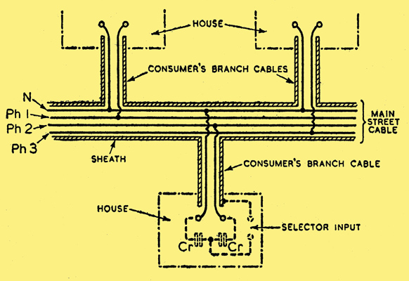
Fig. 4. How current from main street cable (shown in section) is fed to consumers houses. The connection for a 'selector', or mains broadcast receiver, is also shown.
Fig. 4 indicates how the houses get a supply. Branch feeders, having a lead sheath but only two conductors, are joined between any one phase wire and neutral. But to distribute the load evenly between phases, different houses are joined to different phase wires. In effect, a third of the houses are fed from one phase and neutral, a third of the houses from another phase and neutral, and the remaining houses from the remaining phase and neutral. Thus the neutral goes into every house and any one phase into a third of the houses. Each house thus has a single-phase supply.
It will be appreciated that, so to speak, a network of copper and a network of lead bonded together joins groups of houses, anything from 300 to 1,000 in common practice, to a given sub-station. The basic idea underlying our method of carrier current superimposition is to treat all the copper conductors in the street cables as one conductor and all the lead sheathing of the cables as the other conductor. This forms a two-conductor transmission line. Thus, so far as the carrier current system is concerned, we have got to bunch all the copper conductors together at the sub-station. An, outright physical connection of these conductors would short-circuit the mains. But if capacitors of large reactance to the power current (of frequency 50 Hz) but small reactance to the carrier currents (the lowest frequency of which is above 20 kHz) are joined from each phase and the neutral conductor to a common point, then this point taps all the copper conductors in parallel. One terminal of this bunch point is used to form one conductor of a transmission line for the carrier currents, the other terminal being the cable sheath.
This is illustrated by the dotted lines in Fig. 3. Through the four capacitors, C, all the coppers are joined in parallel to one terminal of the carrier current generator H. The other terminal of this generator is joined to the cable lead sheath.
Isolating the Neutral Wire
It is the object of the scheme to raise all the copper conductors to the same carrier potential. It would not be possible to raise the carrier potential of the neutral conductor to the same potential as the phase conductors unless the neutral earth connection were interrupted by a choke L. This is designed to have a high impedance to the carrier currents, but virtually zero impedance to the power currents. Thus so far as the power system is concerned, the neutral remains earthed, but in respect to the carrier currents the neutral is insulated from earth and can be raised to the same potential as the phase conductors. Once this is done, then, clearly at any point on the network all copper conductors have the same carrier potential. Since the domestic load (lights, cookers, refrigerators and so forth) is connected between any one of the phase conductors and the neutral, obviously there is no difference of carrier current potential across the load. So the load may vary between an infinite and virtually zero impedance without disturbing the level of the carrier currents thus superimposed.
Apart from the advantage that, with this method of carrier current injection, there is no necessity to fit an automatic gain control circuit in the house receivers, the scheme has the further merit of minimising 'noises' developed across and by the load.
Because, as is seen from the dotted lines in Fig. 4, showing the connections for energising a house receiver in one house by the carrier currents, one terminal for the input to these receivers is found at the junction of two capacitors Cr connected between phase and neutral. Any disturbances created on the mains containing components in phase opposition develop no voltage at the junction of the capacitors. The majority of disturbances are phase opposed and so are not heard as interference noise.
'Selectors' not Receivers
We like to call the house receiver 'a selector' so as to underline the fact that it has few of the vices of a wireless. It is energised as to its high potential point as described. Its earthy terminal must be joined, in effect, to the lead sheath of the incoming cable. The input impedance of the selector is purposely made very high. Thus if the path between the earthy terminal of the selector and the lead sheath is of high resistance, but lower than the selector input impedance, signals will not be diminished by this high resistance. Thus the earthy terminal of the selector may be connected to the third earthed pin of a three-pin power socket. If this is not provided, then the steel conduit in which the house wiring is run can be used. In the rare cases where cab-tyre two-conductor wiring is used an earth has to be found as for a wireless set.
It is insisted that, so far as the transmission system is concerned, the return is not an earth return, albeit the return conductor is earthed. The transmission line proper - the bunched coppers and the lead sheath - is a concentric cable, and the currents (which may be of the order of one or two amperes because the system is of very low impedance) flow only on the outer surface of the copper and the inner surface of the lead. These currents do not flow, in sensible quantities, in the high-impedance house wiring, nor into the high-impedance selectors; they exist to establish a potential on the low-impedance carrier network.
This rather long, but necessarily long, description, shows how, given a carrier current generator in a sub-station, all the houses fed from that sub-station can be given a programme supply. A thousand houses, at maximum, are fed from one sub-station, the average is more like five hundred. Thus, in order to cover an area, means must be devised to get a carrier current supply to each sub-station.
It would be wasteful to install separate transmitters in each sub-station. Thus our idea is to use repeaters in each sub-station which take a low-level supply from all the transmitters, located at some chosen point in the area, and amplify this to a value suitable for injection into the network. In fact, we require a scheme exactly similar to the power supply scheme illustrated in Fig. 1. That is to say, we want a pair of wires which follow the route of the ring mains, or at any rate which touches all the sub-stations, and which can carry the output of all the transmitters, each sending out separate programmes. This pair of wires must be tapped on to at the substation by the repeater input terminals.
Thus one method to achieve this would be to install all our transmitters at G in Fig. 1, energise the ring main with the carrier currents output from the transmitters, and tap the ring main on to the repeaters at each sub-station. But this presents difficulties. Kilovolts with thousands of kilowatts behind them terrify me, for one thing. Then the ring main has protective gear in its circuit which would impede the carrier currents. Capacitors for by-passing the sub-station transformers would cost a lot of money and might break down. Power engineers hate one touching their sacred HT mains!
Using Inter-station Phone Lines
It is common practice to run ordinary telephone pairs in the same ducts which carry the ring mains. These are used by the engineers for talking from sub-station to sub-station and/or for operating protective gear. Since our currents are of super-audio frequency, we can use these pairs, even if they are being used to carry audio currents, to carry the high-frequency output from one set of transmitters - unique to the system - and distributing this combined output to the sub-station where it is picked up by the repeaters.
Thus, in sum, the basic conception is to install transmitters - as many as there are programmes to be supplied - at some point in the area and to take their combined output on a telephone pair to all the sub-stations in the area. In each sub-station, repeaters, giving equal amplifications to all the frequencies in the complex representing the several modulations of the several transmitters, each having a different carrier frequency, amplify the combined disturbance and feed it into the street cables at a suitable level and according to the scheme previously described.
The reader will, I am sure, appreciate a certain reluctance on my part to give a much more detailed description of a scheme which, owing to the blocking of vested interests, has never had a chance of being put into practice. One must still hope that some happy day we shall be allowed to see if it all works our commercially as well as it has, in demonstration, technically.
Meanwhile the following more quantitative information may be of interest.
Some Data
The power required per programme, per typical street cable, is of the order of 1 Watt. The impedance per typical street cable varies, if not terminated, between 0.5 to 1.5 *Omega;, and is usually inductive. Thus the current per programme is of the order of 1 A per cable. A cable, a Watt, an Ampere, an Ohm is a good rough guide!
We use carrier frequencies, for a six-programme system, of 26, 39, 52, 65, 78 and 91 kHz. These are, in fact, derived from the harmonics of a master oscillator having a frequency of 13 kHz. If the carrier frequencies were not thus 'cogged' - if, in other words, each transmitter had a separate drive the peak voltage of the combined equal output of all transmitters would be six times the peak voltage of one. This would require a repeater dealing with 36 times the power of one programme. By cogging the frequencies the peak voltage of the combined disturbance may be adjusted so that the repeater power is only a little more than six times the power required for one programme.
The lowest 'house voltage' on a typical network energised by powers of the order given above is about 300 millivolts. This gives the required signal-to-noise ratio.
We have demonstrated a selector giving noiseless reproduction when plugged into the same socket as was being used to operate a flashing neon sign. We laugh at vacuum cleaners, refrigerators, light and power switches, and so forth.
The transmitters are designed on the asymmetric sideband principle. This has been discussed in published papers. Suffice it to say that we get a 'level' audio output up to 8 Hz from the very simple and cheap selector, with a carrier separation of 13 kHz. The extra harmonic distortion introduced by the asymmetric principle is of the order of 2% at 1.5 kHz; less at zero or other frequencies.
Our object has been to make the selector (house receiver) cheap to manufacture, easy to operate and pleasant to listen to. The superheterodyne principle is used and there are two stages, one a frequency changer, the other a combined second detector and output valve. The maximum 'undistorted' power output is 2 Watts; quite enough (too much?) for an average room.
There are two filters; one preceding, the other following, the frequency-changer valve. The first filter deals with the signal-frequency currents and has settings to give it the same band width of response over the six bands of frequencies representing the six-programmes. The filter following the mixer and dealing with the intermediate frequency currents has, as in common practice, a constant performance.
The user has no fine tuning to do. A rotating switch is provided which clicks into any one of six positions. Only when the click mechanism registers can the programme be heard. Thus no mistakes can be made; the filters are designed to give their correct responses at the given setting. This exact design is made feasible because the carriers are, compared with radio practice, of much lower frequency. The minimum ratio of maximum side band to carrier frequency is (say) 99 to 91 = 1.09 in the wire broadcasting system, but is 1,000,000 to 1,005,000 = 1.005 in average radio practice. This makes filter design for the carrier current scheme ever so much simpler.
The quotations we have had for manufacturing the selector in quantities shows that the cost is far less than for a radio receiver of comparable performance. But what can a radio receiver give, in variety of choice of programmes with clear reproduction - considering the carrier separations and relative leveIs - compared with a wire broadcasting system such as I have attempted to describe?
In parts of the UK the Rediffusion company offered a wired system of six stations - selectable by a rotary switch - from the late 1920s to around 1970. The mains scheme never operated, but power line point to point internet within a building does exist. Using telephone line twisted pairs to transmit baseband audio - the telephone - and a carrier with multiplexed signals became viable almost 40 years after this article - we call it the broadband internet. Ed
|