|
Wartime modifications to a well-known design.
In its original form the Wireless World Push-pull Quality Amplifier had for its output stage a pair of PX4 valves in push-pull, operated at slightly less than the makerbs rating and giving some 4 Watts output. They were fed from a penultimate stage having a pair of MHL4 valves in push-pull with resistance-capacity coupling. The power unit was built on the same chassis and arranged for energising a speaker field and running a small receiver for driving the amplifier. No special input system was provided, and the amplifier required an input balanced to earth in the conventional push-pull form. Several feeder units of different types, requiring a single-phase input and delivering a push-pull output, were described for driving the amplifier.
From time to time during the nine years that have elapsed since the amplifier was originally described modified versions have made their appearance. The changes made in these later amplifiers have all fallen into one or other of two categories. Some changes have been made because it has been found that the same performance could be obtained more simply or with an economy of material. Among these, the most notable is the adoption of a common cathode-bias resistance for each pair of push-pull valves, leading to the saving of one resistance and two electrolytic capacitors in each stage. Other changes have occurred because valve makers have changed the rating of their valves. PX4 valves, for instance, were changed from a rating of 48 mA at 250 Volts to 48 mA at 300 Volts. By adopting the higher rating a considerable increase of output became possible.
Initially the PX4 valves were operated at 250 Volts, 35 mA apiece. This was adopted chiefly because the maximum current rating of a single rectifier valve at that time was 120 mA, and it was desired to have a reasonable surplus current for the rest of the apparatus. It was found, too, that a really undistorted output of 4 Watts was obtainable, and this was considered to be ample for nearly all domestic requirements. At the present time there are many of these amplifiers in existence, and even now one would be hard put to it to design one having a better performance. The purpose of this article, therefore, is not to indicate any improvements that can be made, but rather to stress the simplifications which are possible without affecting performance. This is particularly necessary at the present time because components are hard to get and, in the event of a breakdown, it may be found desirable to rearrange the amplifier to a more economical circuit than the original one.
The amplifier is still based on the PX4 valve for the output stage. In the interests of valve life, it is recommended that the original rating adopted for this amplifier of 250 Volts, 35 mA be employed. The life at the maker's full rating is quite a reasonable one, judged by peace-time standards. But, at a time when one is lucky if one can obtain a replacement at all, this is not good enough, and it is a wise plan to extend the life by under-running the valve somewhat. The anode dissipation at the recommended conditions is only 8.75 Watts per valve.
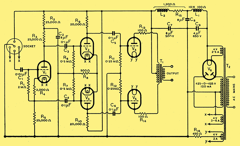
Fig. 1. A wartime version of the Quality Amplifier; complete circuit diagram with values, including phase-splitting input stage. The rectifier valve V6 may be a U12/14 or similar type. Except where otherwise indicated the voltage rating of condensers should be not less than 350 Volts, while resistances can be the usual 0.5 Watt type.
The circuit diagram of the complete amplifier, including a phase-splitting input valve, is given in Fig. 1. If the coupling resistances and valves are balanced, the amplifier in whole and in part is balanced, and feedback effects do not occur in spite of the lack of decoupling. In practice, even if perfect balance is not achieved, the overall unbalance is not great. The common cathode resistances help here. In a push-pull stage having a common cathode resistance, if one side amplifies more than the other, so that the alternating anode current of one valve is greater than that of the other, there is negative feed-back on the higher gain valve and positive feed-back on the lower gain valve. There is thus an inherent self-balancing tendency in each individual push-pull stage.
An amplifier built to this circuit diagram has been in regular use for the last five years with complete satisfaction. During this time the only repair or replacement needed was to one electrolytic capacitor in the smoothing circuit. The original valves are still in use. By adopting this economy circuit, therefore, one need have no fear of any deterioration of performance or reliability.
Leaky Coupling Capacitors
A word of warning is advisable in connection with the coupling capacitors, however, and this applies to any resistance-coupled amplifier. 'New' capacitors available to-day are probably old stock, and capacitors from the junk box are certainly old stock. If the capacitors have not been stored in a really dry place it is quite probable that a certain amount of moisture has found its way inside, with the result that they leak somewhat. An old capacitor from a set which has been in regular use is less likely to leak than one which has been stored away in a drawer, because the internal heat in the set will have tended to keep it dry.
If a coupling capacitor leaks, it means that a part of the steady anode voltage of the previous valve is applied to the grid of the next, seriously affecting its operating conditions. In the case of the early stages no damage is likely to result, because the various circuit resistances limit the current to a reasonably safe value. With the output stage, however, matters are very different. A leak in a capacitor coupling to the grid of an output valve may result in such a heavy anode current that the valve will soon loose emission. When that occurs the other output valve will be under-biased and may also be damaged.
It is, therefore, very necessary to check coupling capacitors for leakage. This can readily be done in the amplifier itself. Place a milliammeter in the anode circuit of the valve immediately following the capacitor, and note its reading carefully. Then short-circuit the grid leak of that valve. The reading now obtained should be identical with the first; if it is lower, the capacitor is almost certainly leaking and should be discarded. The test is somewhat better if the valve immediately preceding the capacitor is removed, since a somewhat higher voltage is then applied to the capacitor. If one cannot replace a slightly leaking capacitor at once, one should keep a careful watch on it and check it regularly, for small leaks almost invariably become big ones in quite a short time. For instance, if it is found that the current of one PX4 valve drops from 36 mA to 35 mA on short-circuiting its grid leak, one would have no cause for worry, provided that one could be sure that the capacitor would get no worse. The difference in performance caused by such a leak would be negligible, but there is a strong probability that within a few weeks the leakage would so increase that the life of the valve would be seriously endangered.
Considerable latitude is possible in the mains equipment. The transformer rating shown provides sufficient surplus voltage for energising a 1,250 Ω speaker field and sufficient current for a reasonably large receiver to drive the amplifier. The speaker field itself is, of course, connected in place of L2 and R15. If it is not desired to energise a field, these components are needed for smoothing and to drop the voltage to the correct level. Alternatively, and more economically, the resistance R15 can be omitted and the mains transformer winding reduced to about 350 Volts only. This will permit the rating of the reservoir capacitor C9 to be reduced to about 500 Volts. On the other hand, if a transformer of higher voltage is available, there is no reason why it should not be used provided that the value of R15 and the rating of C9 are increased appropriately.
Substitute Valves
All this is satisfactory as long as one has PX4 valves to use in the output stage. The early stages, including the phase-splitter, are not critical, and while the MHL4 type is recommended, the MH4 or equivalent types can be substituted with but little effect provided that the push-pull pair are of the same type; component values are unchanged.
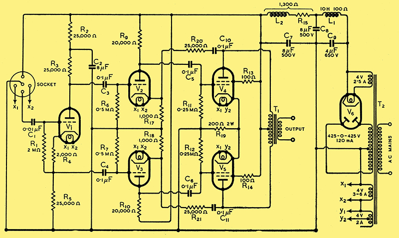
Fig. 2. Modification to allow the use of American-type tetrodes in the output stage, with negative feedback. In this form, the output of the amplifier is about 6 Watts. An indirectly-heated rectifier (MU12/I4 or similar) should be used in order to obviate undue HT voltage rise.
As the maker's rating of the PX4 valve exceeds 10 Watts, even replacement valves are not obtainable without a licence. Even then they are hardly easy to get. It is, however, possible to use the American type 6V6G, and this is believed to be more readily obtainable. A licence is also needed for this valve. The 6V6G is an indirectly-heated beam-tetrode with a 6.3 Volt heater and an octal base. It is, therefore, necessary to change the valve-holders and to arrange for a 6.3 Volt heater supply. This last is easily done, for 6 Volts can be obtained by connecting one half of the PX4 winding in series with the 6 A winding, as shown in Fig. 2. It is necessary to find by trial the correct connections for the 'PX4 winding' since the voltage applied to the 6V6G valves will be either 6 Volts or 2 Volts according to whether the two windings assist or oppose each other. The difference is large, however, and there is no difficulty in deciding by the brightness of the glow of the cathodes which are the correct connections.
The 6V6G is a tetrode. It can be used as a triode by strapping screen and anode. Unfortunately, it is not nearly such a good triode as the PX4, and a pair will not give much more than 2 Watts output. Ample output with low valve distortion can be obtained using the valves as tetrodes, however, but, because of their high AC resistance, transformer distortion will be high unless negative feed-back is used.
Feed-back is easily introduced, and the simplest arrangement is shown in Fig. 2. Independent cathode resistances are now used in the penultimate stage, and a resistance and capacitor in series are connected from each output valve anode to the cathode of the valve feeding it. The values shown give an effective output resistance about equal to that with PX4 valves, and a similarly low distortion level is secured. With 1 kΩ cathode resistors for the MHL4 valves, the feed-back resistors R20 and R21 should be 25 kΩ.
Using this arrangement the performance, with one exception, should be the same as that of the original amplifier. The exception is in the input required, which will be nearer 7 Volts peak than the original 3.5 Volts. The reason for this lies partly in the lower mutual conductance of the 6V6G valves. It is a fortunate circumstance that the 6V6G valves need the same load impedance as the PX4 type under the conditions adopted - namely, 10 kΩ total - so no change in the output transformer is required.
Turning now to methods of feeding the amplifier, the possibilities are so many that one cannot do more than indicate briefly some of the arrangements. For gramophone, a single-stage pre-amplifier giving bass-boost to correct recording deficiencies is all that is necessary in most cases. Two stages may be needed for an insensitive pick-up.
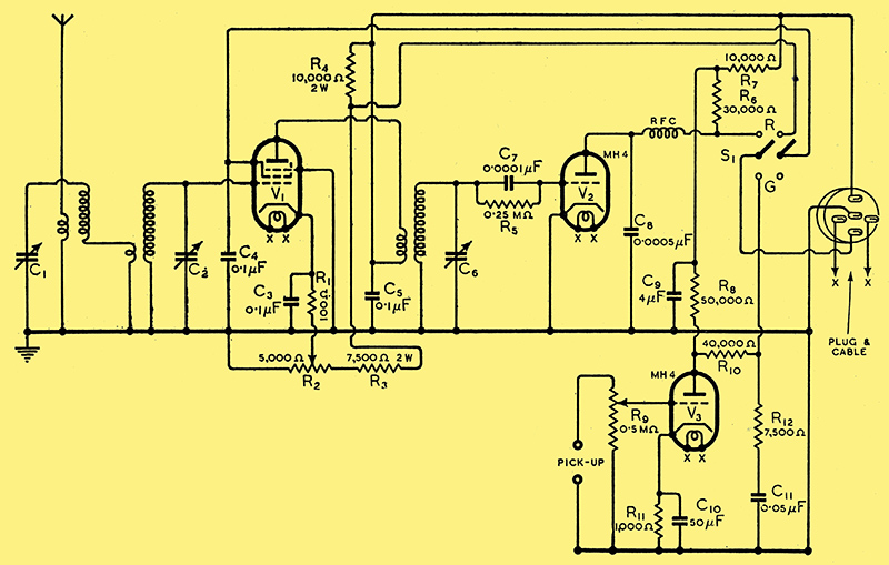
Fig. 3. A radio-gramophone unit for use with the amplifier, to which it is connected by the multiple plug shown. C10 should be an electrolytic capacitor of 12 Volts rating.
This arrangement with a simple receiver is illustrated in Fig. 3, where R9 is the gramophone volume control and V3 the pre-amplifier. R12 and C11 give a fixed degree of bass boost, and S1 is the radio-gramophone switch.
The receiver is a simple RF detector set without reaction and with three tuned circuits. Selectivity is ample for local reception, and the gain is sufficient for short distance work with even a very poor aerial. The set is not intended for anything but the reception of nearby stations. Gain control is carried out by varying through R2 the cathode bias on the RF valve, which should be of the variable-mu type.
Separate valves are used for the detector and the gramophone pre-amplifier in order to save switching in RF circuits. This circuit was adopted largely because an existing receiver was modified, and it was necessary to avoid altering the panel layout. The extra switching needed to make the detector act as the gramophone pre-amplifier and so save a valve, could not readily be introduced, and it was simpler to use an extra valve than to carry out extensive mechanical alteration of the set. Actually, it is not as uneconomical as it looks.
|