|
New Magic Eye Circuit for calibrating AF oscillators.
Aural methods of frequency comparison suffer from the disadvantage that a considerable amount of skill is necessary before two audio-frequency notes, one variable at will, can be accurately and speedily matched together by the 'zero-beat' method. Furthermore, for checking a continuous frequency drift extending over a fairly long period, the presence of two audio-frequency notes becomes tiring to the ear. Another major disadvantage is that accurate harmonic comparison is not always possible.
The visual method by means of the cathode-ray oscilloscope has the advantage of being capable of a higher order of accuracy than the aural measurement, and harmonic comparison up to about 10:1 is available by the use of Lissajous figures. The main disadvantages are the cost and bulk of the apparatus required.
In the method about to be described use is made of a 'magic-eye' cathode-ray type tuning indicator, where the shadow angle varies at the beat frequency. Whilst this system is not intended to replace aural measurements entirely, if used in conjunction with a preliminary aural test to set the variable source approximately to the desired frequency it forms a convenient means of following a continuous drift in frequency, using, the 'zero-beat' method and obtaining the frequency from the calibration of the variable oscillator.
Where several measurements are being carried out simultaneously in close proximity to one another, for aural measurement the use of headphones becomes necessary, with consequent fatigue and restriction on the movements of the operator. By the use of the visual indicator audio interference is eliminated and fatigue minimised. This principle is already commonly used for the synchronisation of the two RF generators in beat-frequency audio oscillators.
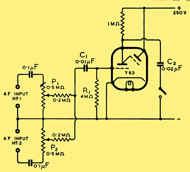
Fig. 1. Basic circuit of visual audio frequency comparator.
The AF indicator consists of a normal 'magic-eye' cathode-ray tuning indicator with the triode pre-amplifier section operating non-linearly after the manner of a grid-leak detector as in Fig. 1.
The two audio-frequency inputs are applied through suitable attenuating and DC isolating networks to the grid of the tube. Although the values of grid leak and capacitor are not critical, it is necessary that the capacitor C1 should offer low reactance compared with R1 to the frequencies being measured, and that the time constant of R1C1 should be sufficiently small so that the capacitor has time to discharge through R1 before the succeeding beat recharges it. Grid-leak rectification takes place in the grid circuit and the grid potential thus varies as the difference between the two frequencies by virtue of the 'additive' mixing; and as the triode anode is internally connected to the shadow grid, the shadow angle varies in sympathy. Due, however, to persistence of vision and after-glow of the screen, the opening and closing of the eye shows up as a general deflection with blurred edges to the shadow. Hence until the two applied frequencies are within some 20 Hz of one another, the actual movement of the shadow is not perceptible, as the shadow angle is varying more rapidly than the human eye can follow it. As zero-beat is approached the eye opens and closes more and more slowly, until at true zero-beat the shadow angle remains constant.
Harmonics
If frequencies f1 and f2 are being compared, the anode current contains components of frequencies f1, f2, f1 ± f2, and also nf1 and mf2 where n and m are integers. These additional frequencies are due to the non-linear characteristic of the tube. This harmonic content will normally be small compared with the amplitudes of f1 and f2 so that when f1 and f2 are nearly equal the edges of the shadow are not perceptibly blurred. In order to assist in achieving a clean edge to the shadow, it is desirable that the amplitude controls P1 and P2 be adjusted so that the amplitudes of the two components of the anode current which will beat together are approximately the same, and that the total effect is to reduce the shadow angle to about half the no-signal value.
In addition to its use as a comparator for two inputs of the same frequency, the indicator, due to its non-linear characteristic, is also capable of being used as a harmonic comparator up to ratios of about 12:1. For, suppose that two frequencies f1 and f2 are applied, and f1 is approximately equal to nf2 where n is any integer less than 12, then the shadow angle will vary at a frequency (f1 - nf2), as the two components of the anode current of frequencies f1and nf2 will beat together. As the ratio of the two frequencies becomes more nearly integral, the opening and closing of the eye becomes slower and finally the shadow angle remains constant when f1 = nf.
Due to the fact that the amplitude of the nth harmonic of f2 is small compared with f2, for this harmonic to be comparable in amplitude with the other input f1, it follows that the amplitude of f2 will have to be very much greater than that of f1. Hence there will be a comparatively large component of the anode current of frequency f2 and the shadow will be rapidly deflected to and fro at this frequency, causing blurring of the shadow edge and difficulty in observing the slow movement of the shadow.
It is thus desirable to eliminate this component of frequency f2. Since the ratio of maximum perceptible beat frequency to the lowest frequency likely to be compared is of the order of 1:5 the frequency f2 can be eliminated by differential bypassing. The choice of the bypass capacitor C, is a compromise, and 0.02 μF is suggested where the lower frequency limit is about 150 Hz. A higher value will mean that the device will be insensitive to beat frequencies greater than about 20 Hz, whilst a lower value will mean that if f2 is low a substantial component will be present across the anode load resistance, giving rise to a blurred image. By this bypassing, accurate measurements up to the 12th harmonic or sub-harmonic are possible. The tube will also give an indication of the frequency ratios 3:2 and 3:4, but, due to the high harmonics necessary, the change of deflection is very small when higher integers are involved. The author is indebted to Mr A H Morser for having suggested the foregoing additional application, and also for the method of obviating the 'halation' produced.
When used as a comparator for two inputs of the same frequency the bypass capacitor is unnecessary. Its absence provides a check, as with all the other ratios the shadow edges will be blurred and a clear image will not be produced when the two inputs are in exact harmonic relationship. An on-off switch, which may be of the ordinary toggle type, has therefore been included so that C2 may be switched in at will.
The indicator and small associated components could be built into an AF oscillator and could then be used either to assist in direct frequency measurement, or, by the injection of a voltage of known frequency, to give calibration check points at the harmonics and sub-harmonics of the injected signal. If a valve maintained tuning fork, or other source of constant frequency of about 500 Hz were available, the range 50 - 6 kHz could be checked in a few minutes.
|