|
Explaining their operation.
During the past few years the focus of interest in radio engineering has been rapidly shifted towards the use of higher and higher frequencies. It is well known that a valve having a conventional electrode structure becomes progressively less and less efficient as a generator or amplifier as the frequency is increased; beyond approximately 100 MHz it may be considered useless for purpose.
Although generators for the ultra-high frequency have been available for several years it had not in general been found possible to secure operating efficiencies comparable with those easily achieved at lower frequencies, and considerable research was, in consequence, devoted to improving this position. Much interest was aroused, therefore, when in 1936 and 1937 announcements appeared in the American technical Press of ultra-high-frequency generators called 'rhumbatrons' and 'Klystrons', for which high efficiency was claimed. The outbreak of hostilities in Europe and the attendant increased importance of the ultra-high-frequency field has resulted in little information being published here on recent developments of these generators.
Space-charge Influence Effect
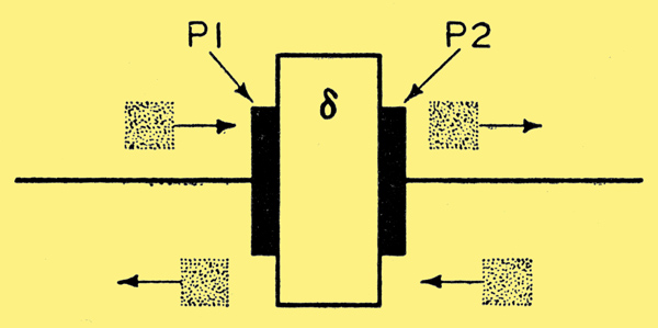
Fig. 1. A simple parallel-plate capacitor, showing diagrammatically the relative movement of electron charges.
The first operating principle is that, for an alternating current to flow in a conductor, it is not necessary for the generator to have a conductive connection with the conductor; it may be readily induced by a 'space-charge' whose density is made to oscillate. This may be made clear by considering the simple capacitor of Fig. 1. P1 and P2 are plates of equal area and thickness separated by δ, a dielectric medium. When the capacitor is discharged the potential difference between the plates is zero and no lines of electrostatic force, pass through the dielectric. If a charge or quantity of electrons is added to P1 a similar charge or quantity of electrons will depart from the surface of P2; that is, a current will flow within P2. Similarly, if the charge applied to P1 is continually imposed and withdrawn, the current within P2 will alternate in direction. It is obvious that P1 here performs the function of a conduction means whereby the proximity to P2 of a quantity of electrons or charge may be varied. This result may equally well be achieved by using a thermionically emitted electron cloud or space-charge, and varying its density or position with respect to P2, causing a varying current to flow in it. This is the modus operandi of the troublesome effect met with in certain frequency-changer valves where the oscillations generated in the oscillator section causes an oscillating space-charge to appear before the signal grid; thus undesirable coupling occurs between the two. Consideration of the foregoing will show that, for adequate power to be induced in a load connected between the two real or effective plates, this load must possess adequate impedance. In practice, as the frequency of alternation becomes progressively higher, a high impedance becomes more difficult to develop; high resistances become short-circuits and above 100 MHz conventional resonant circuits become impracticable.
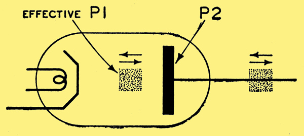
Fig. 2. A capacitor in which one effective plate is formed by an electron cloud or 'space-charge'.
This leads to the second operating principle:-
Cavity Resonators
In 1894 Sir Oliver Lodge demonstrated to the Royal Institution that if an electromagnetic generator be placed within a suitably constructed hollow pipe, the electromagnetic energy could be confined within the pipe during its travel along it and projected as a beam from the open end. The mathematical theory of these 'wave-guides', as they have later been called, was developed by Lord Rayleigh in I897, and from then until 1936 their possibilities seem to have been overlooked. In that year, however, W L Barrow and G C Southworth published results of their independent experiments on guided waves in hollow pipes, and these papers have been followed by many others. It has been found that by so arranging the physical dimensions it is readily possible to develop standing waves in a hollow pipe system, the resulting configurations, called 'cavity resonators', having high impedance and convenient practical construction. Various types of wave are possible in cavity resonators and are differentiated solely by the relative disposition of the lines of magnetic and electric force. They may be excited by placing a loop at right angles to the magnetic lines of force (magnetic excitation) or by a conductor or electron stream parallel to the lines of electric force (electrostatic excitation). This last method of excitation, by an electron stream, is of interest here. Its practical realisation raises difficulties, however, and their solution is dependent upon the third operating principle:-
Velocity-Modulation and Phase-focusing
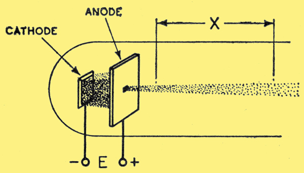
Fig. 3. Simple generation of an electron stream.
At low frequencies and in a vacuum electron velocity is so great and consequently the 'transit-time' or time taken by an electron to move from point A to point B in a circuit is so short, that no error arises in considering the velocity to be infinite. At ultra-high frequencies, however, the transit-time may become comparable to the period of one cycle, and the induction by oscillating space-charge as given above is complicated thereby. A consideration of this problem is therefore desirable.
The velocity of an electron in a vacuum is dependent upon the square root of the fall of potential through which it passes. Electrons issuing from the hole in the anode shown in Fig. 3 will continue with a velocity given by the formula:
ν = 6 × 10⁷√E
where ν is the electron velocity in cm/sec. E is the anode voltage in Volts.
At this velocity the electron stream will traverse a distance of x cms in t seconds, where t = x/v. It should be emphasised that this time may be varied at will by changing the anode voltage E, practical considerations imposing upper and lower limits to this variation. As shown in the description of the first operating principle of inducing an oscillatory current in a conductor by means of an electron cloud or space-charge, the density or proximity to the conductor of the charge must be varied at the frequency of the desired oscillation. An electron stream generated as shown in Fig. 3 may be arranged to do this at moderately high frequencies by interrupting the flow of electrons at such a rate that a cloud of electrons arrives opposite the conductor, and in consequence the conductor receives a pulse of energy in phase with the resonant frequency of the load connected to it. This is shown diagrammatically in Fig. 4.
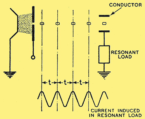
Fig. 4. Excitation of resonance by pulses of current induced by an interrupted electron stream.
This method is impracticable at ultra-high frequencies, however, for two reasons:-
- The difficulty of securing a resonant load having a sufficiently high impedance at these frequencies. In consequence a resonant cavity must be used.
- The physical dimensions of a suitable cavity necessitate considerable length along the axis of the electron stream. The transit-time of this stream will therefore normally be equal to the period of several cycles of the resonant frequency of the cavity.
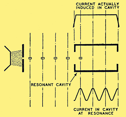
Fig. 5. Showing failure of an interrupted electron stream to induce resonance in a conductor having considerable length along the axis.
The significance of this latter disadvantage may be appreciated by reference to Fig. 5. During the whole of the time that the electron cloud is within the cavity, it has the same influence upon it irrespective of its position (as shown in the upper diagram); whereas for resonance to be excited, the influence should vary as shown in the lower diagram. This might be overcome by making the velocity high and the transit-time short, but this would necessitate increasing the voltage E. Since the power supplied to the generator increases as the square of E (P = E2/R) and the velocity only increases as the square root of E (ν = 6 × 10⁷√E), the efficiency falls more rapidly, due to the increase of energy supplied, than it rises due to reduced transit-time effect.
The solution to the above dilemma may be appreciated by considering a well-known schoolboy problem in mathematics: b If a train A starts with a velocity ν1, and T hours after a second train B starts with greater velocity ν2, how far must they travel before B overtakes A? Assuming this to be solved, suppose that at the point at which B overtakes A there is a level crossing, the gates of which have been negligently left closed; it will be obvious that the energy available for the immediate destruction of the gates will be greater at this point where the trains run side by side than at any other point on the line where one runs in front of the other.
If this principle is applied to an electron stream, the velocity of successive electrons of which is made successively greater, it will be apparent that at one point all electrons will overtake one another to form a 'bunch' and that the influence effect of this bunch at the point of its formation will be greater than that of its component electrons at any other point. In the case of the cavity resonator and electron stream given above, it is possible by suitable design to arrange the bunch to occur once per cycle at, for instance, the point where the stream leaves the cavity. Then, spread out along the stream behind the bunch will be electrons travelling with varying velocities, the net effect of which (some aiding and some impeding the resonant flux) will be very small compared with the large effect of the bunch.
The elements of an efficient ultra-high-frequency generator operating on the velocity-modulation principle are, therefore:-
- Source of electrons and suitable accelerating and focusing means.
- A device to impress a variation of velocity on the electron stream (buncher).
- A resonant cavity to receive the energy from the buncher in suitable form (catcher).
- Coupling means to ensure correct inter-operation of buncher and catcher.
- DC return path for the electron stream after passing through the system.
Practical Embodiments
The development of the first generator to operate on the velocity-modulation principle is commonly credited to R H Varian and S F Varian, who in I936 published details of their Klystron generator. In 1933, however, Arsenjewa-Heil and Heil gave details of a device rather similar to the Monotron, to be described later. The method of function was only generally indicated, but there seems little doubt that it was, in fact, the first of the velocity-modulation generators.
The Klystron
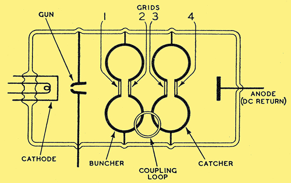
Fig. 6. Essential elements of a Klystron generator. Electrons generated at the cathode are formed into a beam by the gun, whence they pass to the buncher. The buncher varies the velocity of successive electrons and they form bunches just inside the catcher.
Fig. 6 shows the Klystron as it was originally described. The buncher and catcher resonators of identical shape and having, in consequence, identical resonant frequencies, are in the form of toroids in which the re-entrant portions, instead of meeting at the centre, are closed in each case by two grids: 1 and 2, 3 and 4. It was shown in Fig. 3 that a variable velocity could be imparted to an electron beam by passing it through an electrode to which a varying potential was applied. To attempt to secure this velocity modulation with a single electrode would be to encounter the same difficulties as in a conventional valve, and a cavity resonator must be used. The operation is then as follows: assuming oscillations to have been started, oscillatory energy would be fed back from the catcher via the coupling loop to the buncher. As a result of this grids 1 and 2 will alternately become positive and negative with respect to each other at the oscillation frequency; this means that the electric field between them will alternately oppose and assist the acceleration field due to the gun, and a variation of velocity will be impressed on the beam. The catcher is so disposed to the buncher that the electron stream forms a bunch just within it, the incidence of successive bunches exciting it to resonance.
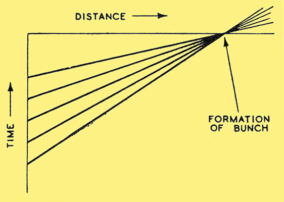
Fig. 7. Showing the velocity imparted to successive electrons arriving after equal time intervals at the buncher.
This explanation is considerably simplified in some respects, but a full understanding can only be achieved in mathematical terms and, in fact, the Klystron has so far defied a complete explanation in such terms. One simplification however, should be immediately apparent from what has already been described: namely, that in a practical Klystron the transit-time within the resonators will be at least an appreciable part of one cycle of oscillation. The electric field will not, in consequence, have a uniform direction during the whole of the transit of the buncher, and velocity modulation must be considered a sum effect of the various accelerations impressed during transit. A simple exercise in integration will show that the effect may be neglected and, when all factors are taken into account, the efficiency is only reduced from a theoretical maximum of 58% to 40% in practice.
The Monotron
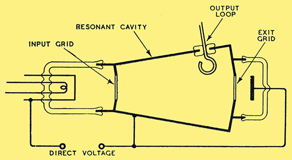
Fig. 8. The Monotron, a simplified version of the Klystron.
Consideration of the voltage relationships Within cavity resonators has shown that the function of buncher and catcher may be combined in one resonator. This device has been called the Monotron and one version is shown in Fig. 8. It will be seen that in this case the resonator has considerable length along the axis of the electron stream, so that during the time of transit several cycles of oscillation can occur. During transit, therefore, the electrons are continually being accelerated and retarded, but since this applies equally to all, the bunching effect is governed only by the variations of potential at the input grid. By suitable physical design and applied voltages the bunching may be made to occur in the right phase just at the exit grid. Another valuable feature arising out of this is that the oscillation may equally readily be quenched by application of an incorrect voltage to the resonator, which fact offers a solution to the hitherto difficult problem of modulation. The simplicity of the Monotron and the fact that, unlike the Klystron, velocity modulation and energy transfer occur at single grids, has led to a concentration of development on this type. The results of these labours must for the present, however, remain a matter for speculation.
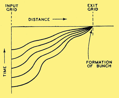
Fig. 9. Velocity diagram of successive electron velocities between input grid and exit grid.
|