|
A compact and easily built design using modern triode-pentodes. Full constructional details are given.
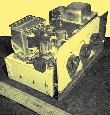
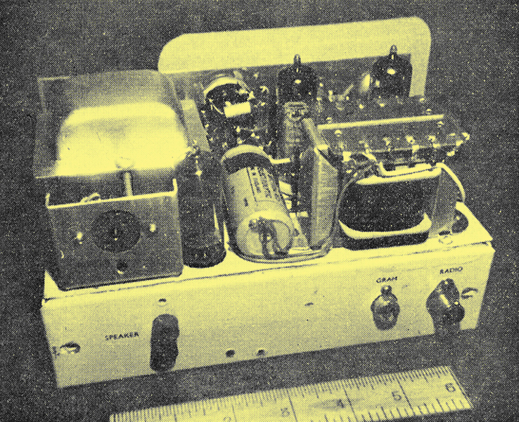
The completed amplifier.
The availability of the ECL86 valve simplifies the construction of a push-pull amplifier capable of delivering some 8 W of good quality audio when fed from a crystal pick-up or a superhet tuner.
The benefits derived from the push-pull circuit are well known, and results surpass those obtainable from simpler single-ended stages. Although some 3-4 W output is often considered adequate for home use it is generally better to design for considerably more than this so that the amplifier is not, amongst other things, worked too hard into a region of high distortion. This frequently occurs when a single- ended Class A stage is in use and it is not unusual to find the volume control associated with such an amplifier well advanced. This is undesirable. The amplifier to be described here was built originally for record reproduction purposes and is an economical proposition. Facilities for connecting a tuner are also provided.
Above chassis view of the rear of the amplifier.
It is not considered a hi-fi amplifier - using the term in the un-debased sense - but it is, nevertheless, surprisingly efficient and very compact, since only two actual valves are required in addition to the rectifier. The chassis dimensions are only 8 x 4 x 2 in.
An output socket is provided from which power supplies may be taken to a valve tuner if required. Some 20 mA HT current is available, this usually being adequate, together with 6.3 V at 1 A. If this facility is not required - as would occur where the use of a transistorised tuner is envisaged - the socket may be deleted and minor economies effected by selecting a mains transformer of lower HT current rating together with a less generous rectifier valve, such as the EZ80.
The Amplifier Circuit
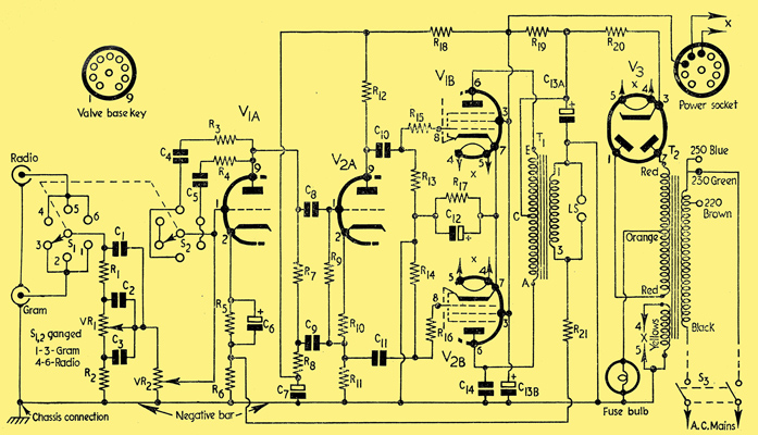
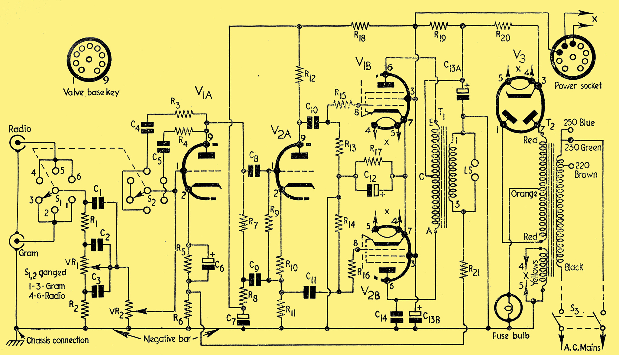
Fig. 1. Circuit of the Useful Push-pull Amplifier.
The amplifier circuit is shown in Fig. 1, where it will be seen that of the two triodes available one is used as a pre-amplifier feeding into the second triode, which functions as a phase splitter. Signals opposite in polarity appear at C10 and C11, and these are fed to the output pair operated here in true pentode mode as opposed to the ultra-linear form. The latter is frequently encountered nowadays but would demand the use of a specially designed output transformer.
A moderate degree of negative feedback is applied to the input triode at its cathode via R21; too large an amount is not desirable here.
The use of a common cathode bias resistor for the output pair provides a degree of automatic current self-balancing but the pentode sections should not be widely dissimilar in their characteristics; ideally they should be matched despite the fact the parallel ageing may not take place.
The Power Supply
Full-wave rectification is adopted and it may be noted that the pentode anodes are effectively supplied direct from the rectifier cathode, R20 merely being a surge limiter. The screen-grids of the pentodes are not fed from this point, however, but via R19 and C13(b). This method obviates the need for a smoothing choke and permits the use of a low wattage resistor for R19. The triode stages are further decoupled and there is no mains hum despite the fact that the heater supply is at chassis potential on one side.
The Output Transformer
This is a comparatively inexpensive item rated at 7-10 W, and is a multi-ratio type enabling 22 single-ended and 17 push-pull ratios to be obtained. The DC rating is 75 mA maximum. The particular specimen used in the prototype tended to 'buzz' during sustained notes around 100 Hz and less although an improvement resulted when the laminations were wedged tightly externally. The addition of C14 was also found beneficial, but if the amplifier is to be much used at high volume settings with full bass boost a 250 V. ACW component is recommended here. The value of C14 in the prototype was 0.005 μF, but this may be increased to 0.01 μF if desired. The connections shown for the output transformer assume the use of a 3 Ω speaker, but if a 15 Ω unit is to be used R21 must be changed to 6.8 k&Omaga; and tags 1 and 5 of the transformer used for the speaker connections.
Tone Control
Experience shows that in any unit designed for general home use the inclusion of a complex array of control knobs is undesirable, for it is not unusual to find the Treble and Bass controls being turned unwittingly by unskilled users to alter volume - even when clearly labelled. Here only three controls are fitted, VR1 being used for Bass and VR2 for Volume. The third control performs a dual purpose in that it not only changes over the two inputs but also acts as a Treble switch.
Of the six positions available on the switch two are probably the most likely to be used, viz., positions 3 and 4. In position 3 the Gram input socket is connected, whilst moving the switch one point to the right connects the Radio socket. If
the switch is so set, i.e. to position 4, and top is considered excessive, a further turn to the right will bring R3 C4 into the circuit and top-cut will occur. Similarly on Gram (position 3) excessive top can be reduced by moving the switch one point to the left - to position 2. Still greater top-cut is possible for either function at positions 1 and 6, but as the amount provided is not likely to be required very often the most inaccessible positions of the switch are chosen for these. Top-cut occurs due to frequency selective feedback from the output to the input of V1A. Individual constructors might like to experiment with different values in the C4 and C5 positions to suit their own tastes. To sum up, the three positions of the switch to left of centre operate on Gram whilst the other three positions operate on Radio. Of the six positions, 3 and 4 are those most likely to be required.
A disadvantage of the arrangement is that the Radio input is not completely muted when Gram is in use, but it is usually possible to slightly detune the tuner to remove any remaining traces of signal present.
Bass control is obtained by VR1. As the slider is moved towards the lower end of the track of VR1 C2 becomes added progressively in series with the signal, and low frequencies are attenuated. At the other end of the track, C3 increases the impedance presented to R1 as the frequency is lowered, and greater output results in this region. Bass cut and boost (approximately 5 and 12 dB respectively) are thus available by means of a single control. The tone and other controls have been so positioned that, if required, the panel to which they are affixed can be removed completely from the amplifier chassis, and in some cases this facility might be beneficial - to suit a particular cabinet for example. Inclusion of an On/Off switch is undesirable with either of the controls since these are at a point in the circuit which is very susceptible to mains hum. In the prototype a switch is inserted in the flexible mains lead. Plenty of space exists on the panel, however, for the fitting of a rotary or toggle switch, if preferred, and/or for the inclusion of a warning lens and lamp.
The Phase Splitter
The phase-splitter circuit is of interest in that the resistors in the anode and cathode circuits of 2(3) are not equal in value, R12 being approximately only one-half the value of R11 (the grid resistor, R9, and the cathode resistor, R10, are merely bias fixing components for the stage). It would seem that use of the values specified would result in unequal signal outputs to the pentode grids. To AC, however, R8 is effectively in parallel with R11 due to C7 and C9, and the loads are thus fairly equal over a wide range of frequencies. The high input impedance of the V2(a) stage enhances the gain of the previous stage, hence the use of this particular circuit.
Layout
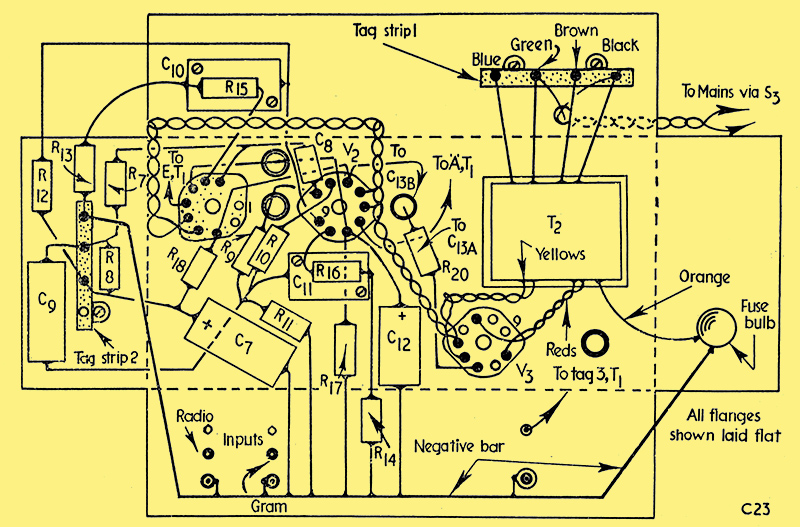
Fig. 2. Below-chassis wiring diagram.
Since only two valve-holders are required to carry the amplifier circuitry, minor problems arise in eliminating congestion and preventing unwanted feedback from occurring. The underside layout of the chassis is shown in Fig. 2 and it is unlikely that this can be much improved upon. Actually it is more compact than it appears here since, in the diagram, the chassis flanges are shown laid out flat for clarity. Note that the amplifier proper is at one end of the chassis and that the power supply is at the other. The photographs accompanying this article further illustrate the layout.
Precautions against mains hum consist of keeping the input and output circuits separated, by tightly twisting together the heater and other leads carrying AC and by using only a single chassis connecting point for the under-chassis components (via a negative bar consisting of heavy copper wire) at the input sockets, thereby helping to eliminate unwanted chassis currents. All wiring associated with V1(a) grid circuit must be screened.
No space exists for group-board techniques, so anchor points are provided by two simple tag-strips, C10 and C11 also assisting here since they are chassis-mounting mica types. Tubular components may be used instead provided Spire clips are fitted to retain them.
Spire clips also retain C6, C9 and C13. Note the location of the fuse bulb, which is fitted to prevent a destructive flow of current if a fault such as a heater-cathode short-circuit developed in V3.
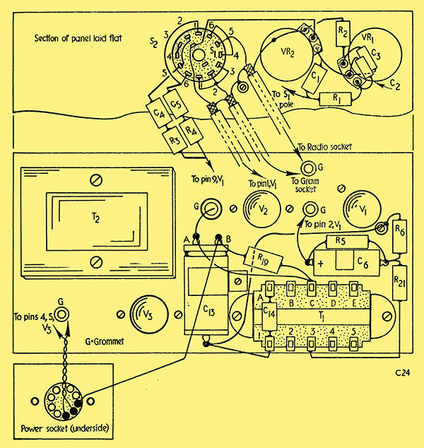
Fig. 3. Above-chassis wiring diagram.
The above-chassis layout (see Fig. 3) is also compact and here, too, the power supply socket and a section of the panel are shown laid flat. Note the space available for a panel-mounted lamp or switch and observe that screened cable is used for the input leads. This screening must be connected to the panel as shown in Fig. 3, the other ends of the screened wires being earthed to the negative bar of Fig. 2. (It should be noted that this method of connection enables the panel to be removed entirely.)
Mechanical Details
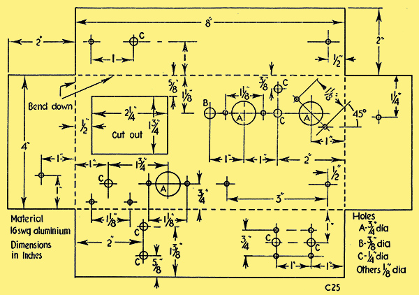
Fig. 4. Chassis drilling details.
Although a 5-piece sectional chassis was used in the original, a standard type may also be employed, and all essential cutting and drilling details (applicable to both types) are shown in Fig. 4.
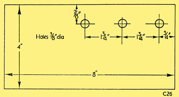
Fig. 5. Panel details.
The panel dimensions, etc., are indicated in Fig. 5 whilst in Fig. 6 details of the bracket needed for the power socket are shown. These items are made from 16 SWG aluminium. Although the panel control holes may be more widely separated, if desired, extra care will need to be taken to avoid mains hum. The panel is held clear of the chassis by ½ in spacers.
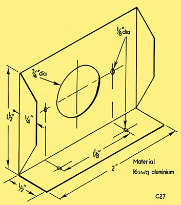
Fig. 6. Dimensions of a suitable power socket bracket.
Constructional Notes
After chassis preparation all major components are mounted, including the panel, the valve-holders being oriented as shown in Fig. 2. Preliminary work consists of bringing up the flying leads of T2, soldering the negative bar in position and wiring the heaters as shown. Grommets must be located at the holes marked 'G' in Fig. 3.
General chassis wiring can then be proceeded with as shown in the diagrams, leaving the panel mounted components and the power socket wiring towards the end. Resistor R21 should also be left temporarily disconnected at the end associated with T1 secondary winding.
Checking
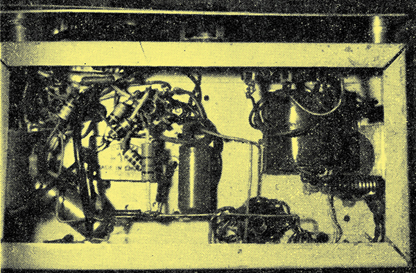
Below-chassis view of the completed unit
Upon completion, a thorough check of all wiring should be made and if all is well the valves and fuse bulb may be inserted as appropriate. With the mains supply plug not inserted in its socket an Ohm meter should be brought into use to ensure that no direct circuit exists between any tag on tag-strip 1 (Fig. 2) and chassis, and that a low resistance reading is obtainable between any two of the tags. The Ohm meter negative test lead should then be clipped to the chassis and readings taken from pins 1 and 8 of V1 and V2; these should be high due to the grid resistors. Fairly low readings should be obtained from pins 2 and 7 of V1 and V2, and from pins 1 and 7 of V3. The positive test prod should next be applied to pin 3 of V3, whereupon the pointer should swing over towards zero then move steadily towards a higher reading as C13 charges. If the pointer continues to read zero a fault exists on the HT rail and the unit should on no account be connected to the mains until clearance has been effected.
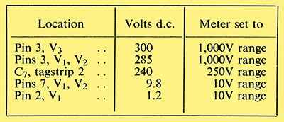
If all is well the test meter should be set to read Volts, DC and the positive prod disconnected. Control knobs may next be fitted and a speaker connected. The amplifier may now be switched on remembering that tags A-E of T1 are HT 'hot spots'! The valve heaters should commence to glow fairly quickly and a series of meter readings should then be taken; these should bear some resemblance to those given in the accompanying Table, which was compiled using a Weston Analyzer with a sensitivity of 1,000 Ohms per volt. If no heater glow is observable switch off immediately and check the wiring after discharging the HT electrolytic capacitors via a resistor of 10 - 20 kΩ.
A Trial Run
If all is well, VR1 and VR2 should be set to approximately 25% of full travel and the rotary switch set to position 3. If the output from a crystal pick-up is now applied to the appropriate input socket on the amplifier via screened cable and plug, the results should be heard in the speaker. The quality should be crisp and clear and the various controls may then be experimented with to become familiar with their functioning.
R21 has yet to be connected and when this is done the volume level should be lower than before for the same setting of VR2; the response should also be improved. Should fierce oscillation occur when R21 is connected, the amplifier should be switched off at once. The oscillation will be due to incorrect feedback phasing, and this may be remedied by changing over the leads to the secondary tags on T1. Changes should not be made whilst the amplifier is switched on.
Conclusion
For normal home use it is not likely that VR2 will need to be turned to more than about half travel when records are being played. The positions used on the switch will depend largely upon the userbs needs, and older listeners are more likely to prefer full 'top' than their younger relations. Switch positions 1 and 6 are most useful when old 78 RPM. discs with noisy surfaces are played.
The amplifier runs at a fairly high temperature and should not be made available for general use until contained in a suitable cabinet, the design of which should permit a flow of cooling air from below. The amplifier should never be run without a speaker being connected.
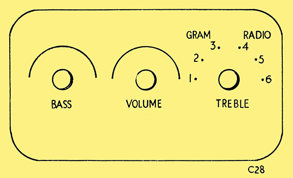
Fig. 7. Suitable escutcheon layout.
An escutcheon may be drawn up (black lettering on a gilt background is effective if faced with clear Perspex) and a suitable outline is shown in Fig. 7, this agreeing with that used with the prototype.

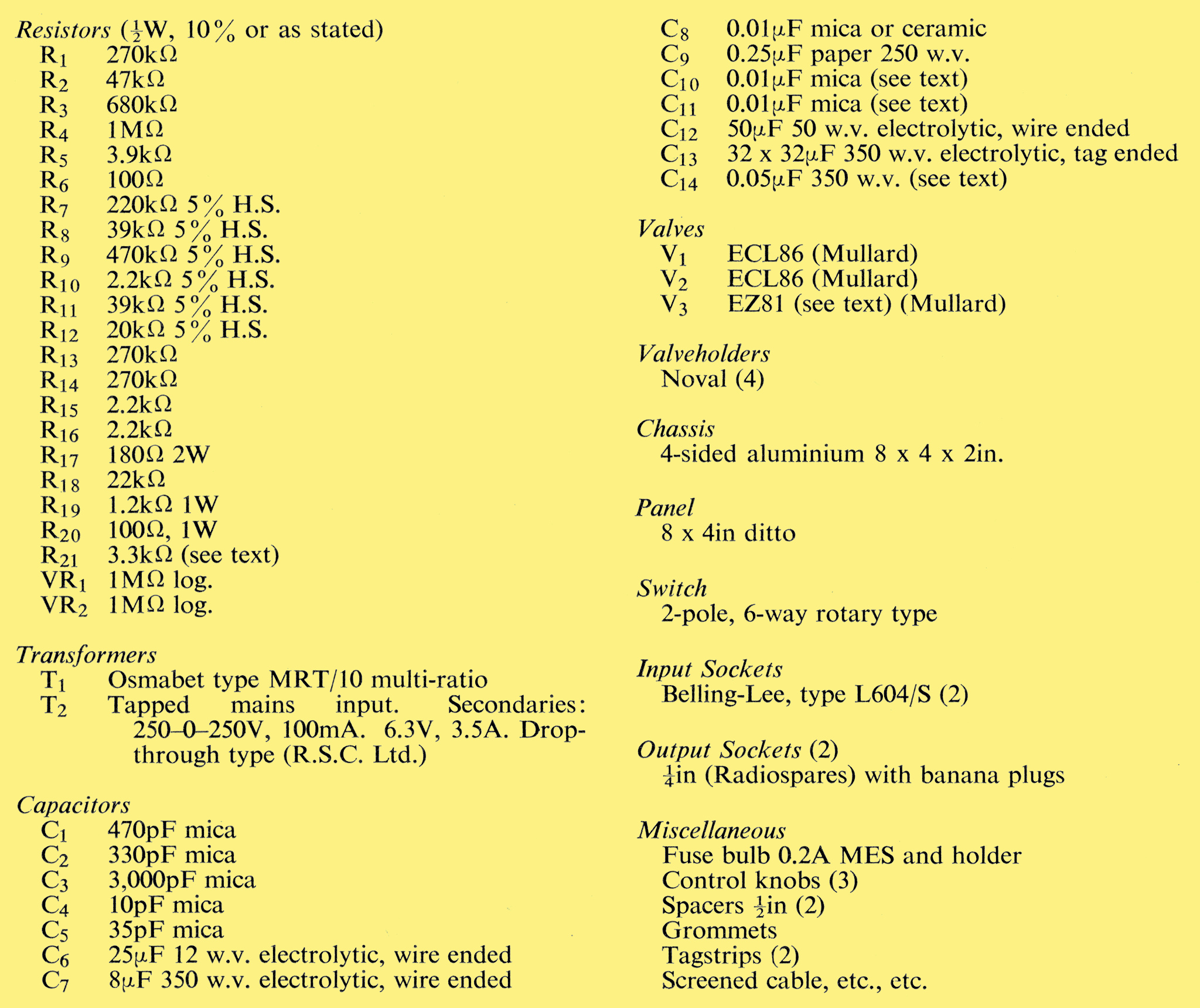
Components List. Valves: ECL86, EZ81 & EZ80.
|