|
A versatile gas discharge relay.
In the previous issue of this journal there appeared an article on a high-speed telegraphic system in which one of the essential elements was a gas-filled relay valve of unusual design. It is proposed in this article to give some further details of this valve which has many useful applications in the electronic art.
In the early stages of development of the high-speed telegraph system in 1934 an ordinary two electrode neon valve was at first used as coupling element and later the Pressler neon relay was tried, but because of its sensitiveness to variations in the HT supply and its instability, it proved unsatisfactory. Better results were obtained by using the Pressler tuning indicator with its third electrode which was normally used for suppressing noises. This meant that for the first time it was possible to maintain the glow in the neon device over its whole working range, instead of the usual switching on and off with each impulse as was the case with the two electrode valve. Unfortunately, however, only a very small output voltage was obtainable from this three electrode device as it was not possible to polarise the voltage on the third electrode without interfering with the proper functioning of the other two electrodes.
At this stage the first improvement was made which culminated in the production of the Teleion. A screen was introduced between the first and third electrode so as to prevent the direct influence of one on the other, and so enable the third electrode to be polarised (i.e. to be held at a voltage more negative than the second electrode with respect to the first electrode).
A scientific controversy arose at the time as to whether it was at all possible to screen one part of a gas-filled valve from the other by means of a metal disc which had to have a hole in the centre to allow for the spreading of the glow along the second electrode. It was maintained that if ionisation took place in one part of the valve it could not be prevented from occurring in the other part of the valve by means of such a screen, and that at best one would still have to contend with the so-called 'dark current'. However, in the same year, 1934, one such valve was actually made and its effectiveness demonstrated.
In I935 a fifth electrode was added in order to reduce the time lag normally encountered in gas-filled valves due to ionisation and de-ionisation. This again provoked a rather prolonged scientific controversy, but later on in the same year it was demonstrated on the cathode-ray tube that by the introduction of this fifth electrode - the so-called 'glow-up' electrode - and by maintaining it in an over-saturated condition, the ionisation and de-ionisation times could be reduced to something negligible.
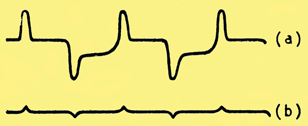
Fig. 1. Variation in voltage across input electrodes (a) without glow-up electrode; (b) with glow-up electrode.
In Fig. 1 are shown the type of traces seen on a cathode-ray oscilloscope of the variation of the voltage across the input electrodes of the Teleion when fed from a beat frequency oscillator (through a rectifier). Curve (a) was taken with a Teleion which had no saturated glow-up electrode whilst curve (b) shows the improvement when using an over-saturated glow-up electrode. The humps in curve (a) illustrate the time and energy which is required to produce ionisation and de-ionisation before the valve operates normally and stabilises its own input voltage. The addition of this fifth electrode meant, of course, that the range of speeds for which this valve could be used had been greatly increased.
With the help of this five electrode Teleion the first successful high-speed telegraphic arrangement was produced in 1937, this being the forerunner of the arrangement which was used with such remarkable success during this present war.
The Teleion in its present form is a gas-filled valve having five basic electrodes.
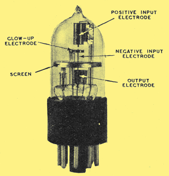
Fig. 2. Principal electrodes in the Teleion valve.
- The positive input electrode, which is a cylinder at the upper end of the valve.
- The negative input electrode, which is a vertical thin wire in the centre of the valve.
- The screen, which is a horizontal plate dividing the valve into two parts.
- The output electrode which is a star-shaped cylinder surrounding the negative input electrode below the screen.
- The glow-up electrode, which is a ring around the negative input electrode between the positive input electrode and the screen.
The input as the name implies is formed by the positive and negative input electrodes. The output is arranged across a suitable resistance which is placed between the output electrode and a potential negative with respect to the negative input electrode. (Fig. 3).
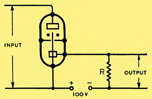
Fig. 3. Method of deriving output voltage.
More electrodes are added to fulfil certain requirements. There is an auxiliary positive input electrode, which is a thin wire inside the positive input electrode one end of which approaches very near to the negative input electrode; more output electrodes may be added and placed in a row below the original one.
The propagation of glow along the surface of a cathode with an increase of current in the cathode circuit, is a phenomenon in gas discharge valves. This principle has been incorporated in the Teleion, using the negative input electrode which contains the glow and the output electrode which is excited by the proximity of the glow. The glow can thus be maintained on the negative input electrode alone or by extending it downwards can be made to touch the output electrode also. This is shown in Fig. 4, where the two conditions for the glow are illustrated.
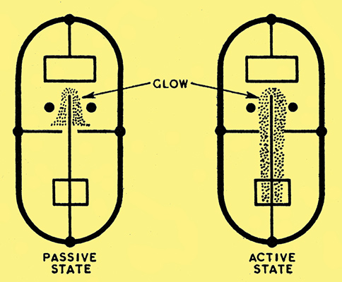
Fig. 4. Extent of glow discharge in the active and passive states.
The following are the general characteristics of the Teleion. As the input current increases, there is at first practically no output current at all, then at a predetermined point the full output current is obtained with a very small additional increase in input current. Then with a further increase in input current the output current may be maintained at a constant value. It is important to add that when this process is reversed - that is to say when the input current is decreased again - the new curve obtained almost retraces the curve obtained for an increasing input current as shown in Fig. 5.
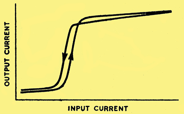
Fig. 5. Input-output characteristic of the Teleion.
Although the change of output voltage across the output resistance is large the input voltage (i.e. the voltage between the positive and negative input electrodes) remains practically constant. This eliminates the Miller effect in the preceding valve more effectively than the screen grid tubes normally employed.
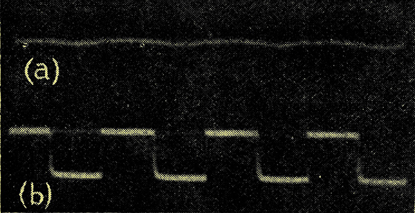
Fig. 6. Oscillograms of input voltage (a) and output voltage (b) at a pulsation frequency of 1,000 Hz.
The traces in Fig. 6 were taken on a two beam oscilloscope, curve (a) showing practically no variation across the input electrodes whilst curve (b) shows the output of an amplitude of 100 volts. These curves were taken at a pulsation frequency of 1,000 Hz and illustrate well why the Teleion has proved so successful in high speed telegraphy. The exponential tendencies on one side of the pulses in curve (b) are due to the stray capacities of the leads to the oscilloscope coupled with the one megohm across which the output was taken.
It is of interest to examine more closely why the Teleion gives comparative freedom from Miller effect. One of the chief characteristics of a gas discharge tube is that the current flow may be varied without varying the voltage across the input electrodes. To control this flow of current a variable series resistance is normally employed. In the case of the Teleion, however, the preceding valve is used as the variable resistance, the control of which is maintained by means of the variation in its grid potential. In Fig. 7 is shown the basic circuit for the parallel connection of the Teleion. It can be seen from the figure that as the supply voltage is constant - particularly as the current withdrawn through resistance R is practically constant and also as the voltage between b and c is constant - the potential at point a must also be constant irrespective of the variation of the grid potential. This means that no contra voltage can be reflected back into the input circuit from the anode circuit by means of the inter-electrode capacities, thus eliminating the so-called Miller Effect.
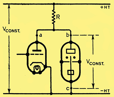
Fig. 7. Basic circuit of Teleion amplifier with parallel connection.
From the characteristics described it will be seen that the Teleion is pre-eminently suitable for the amplification of weak DC pulses such as those derived from the photoelectric cell in a high-speed transmitter or the diode in a receiving circuit. It has also been employed in a sensitive relay circuit of simple design which provides an output of 10 Watts for a change of input capacity of one micro-microfarad, and it has also been used to improve the fly-back in time base circuits. The writer wishes to acknowledge, with thanks, the permission given by M S Lalewicz, the inventor of the Teleion, to use certain information incorporated in these notes.
|