|
A self-balancing phase splitter.
The phase-splitter circuit shown in the February, 1945, issue (p. 38) [*] We need a copy of this issue is an interesting alternative to the several better-known types; but as the primary purpose of the diagram was to illustrate some notes on new Dutch valves - in particular a triode-hexode, which type is not essential to the circuit the layout tended to obscure the basic principle of the phase splitter. It may therefore be helpful to redraw the, circuit in its simplest form as in Fig, 1, using (for the benefit of any who care to make a comparison) the same component numbers as in the original.
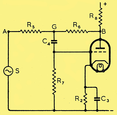
Fig. 1. The see-saw circuit in its simplest form.
A and B are the two points from which are obtained the two anti-phase voltages for driving the push-pull output stage. S is the source of the signal (in practice, almost invariably the output of an amplifier valve), and is itself the drive for one of the push-pull valves. The problem is to provide a second drive, equal in voltage, but opposite in phase. In the well-known paraphase system, the connections are the same as in Fig. 1 except that R6 goes to a point of fixed potential (+ or -) instead of to B. R5 and R6 then together form a potential divider which is adjusted to step down the voltage at A in the same ratio that the valve steps it up. For example, if the voltage amplification of the valve is × 40, the tapping is adjusted to make R5 39 times as great as R6, so that the voltage applied to the grid of the valve is 1/40 of that at A, and the voltage at B equals that at A. The valve provides the necessary phase reversal, and its voltage multiplication exactly offsets the voltage division between A and its input. At least, it is when the tapping is exactly adjusted.
And that is one of the disadvantages of the paraphase method. For it is clear that a very slight shift of the knob controlling the tapping point may cause the voltage at B to become seriously unequal to that at A. A change in the amplification of the valve likewise upsets the balance. It is perhaps not unduly idealistic to aim at a balance in which one output voltage does not differ from the other by more than about 10%. Without instruments of some kind it is not easy to readjust the balance. Now consider Fig. 1, in which R5 and R6 are equal high resistances - of the order of 1 megohm. The easiest way is to assume that the desired result is already I achieved, so that there is at B a signal voltage which is equal and opposite to that at A. Visualising the voltage swings at A and B, and at every point along R5 and R6, as up-and-down movements, we have something like a see-saw. As A goes up, B goes down, and vice-versa. Equal distances along the see-saw represent equal resistance steps (and therefore equal potential differences) along R5 and R6. At the centre, where the grid of the valve is connected, we have the fulcrum of the see-saw, at which the up-and-down movement is nil. In other words, the valve is delivering its output without any grid input, which of course is absurd.
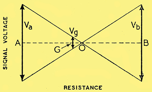
Fig. 2. Diagram showing signal voltage amplitude, as the vertical distance between the sloping lines, at all points between A and B along R5 and R6. As Va and Vb are assumed equal, O, the point of zero voltage, is at the centre point, with equal resistance each side. The required grid voltage is obtained at G, so AG represents the resistance of R5 and GB that of R3. (For clarity, V is exaggerated, here and in Fig. 3.)
But there is no need to be too downcast about this fiasco, because if the grid input connection is moved very slightly away from the electrical fulcrum towards A it will get an adequate signal voltage in the correct phase. Suppose again, for example, that the voltage amplification is 40. Then the grid tapping need be shifted only one-fortieth of the way from the centre to pick up the required voltage. This can be seen quite easily in the see-saw voltage diagram, Fig. 2, in which, if OG is 1/40th OA or OB, the voltage swing at B is -40 times that at G, which is what we have assumed as the performance of the valve. The ratio GB/AG is then 41/39. Electrically, this requirement is met if R6 is 41/39 (or 1.05) times R5, or in other words 5%. more than R5.
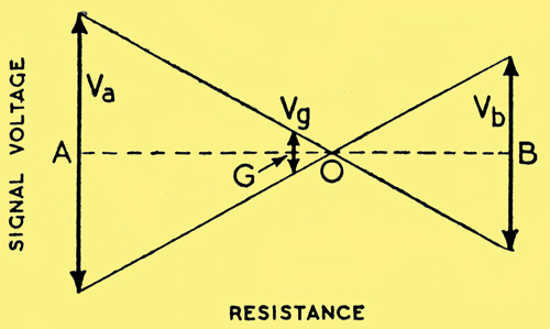
Fig. 3. Here R5 and R6 are assumed equal, so G is the centre point, and O is displaced. Vb is therefore less then Va; but the difference is small if Vg is very small compared with Vb.
It might appear at first that unless this small percentage difference is accurately maintained the system will not work properly; in particular, if the resistances were exactly equal it would not work at all. Fig. 3, however, will show that it was a mistake to jump to the conclusion that equal resistances are no good. Here the vertical line representing the grid swing has been drawn at the centre of the 'see-saw' and one-fortieth as big as the swing at B. By joining up the corresponding arrow heads by means of the two sloping lines that indicate by the vertical distance between them the voltages at all points, it can be seen that the fulcrum is shifted slightly towards the B end, while the swing at the A end has to be slightly increased. A little elementary geometry shows that the voltage swing at B is now 5% less than that at A - a quite tolerable departure from strict balance. Even if the resistors were the wrong way round, so that R6 would be 5% less in resistance than R5, the error in balance would be Within 10% If the amplification of, the valve is greater than 40 (as can quite easily be arranged) the vertical swing at G is even less compared with that at B, the fulcrum O is consequently nearer the centre still; and the A and B swings become still more nearly equal.
The great merit of what may appropriately be called the see-saw phase splitter circuit should now be apparent - its self-balancing properties. So long as the resistors R5 and R6 are equal within commercial limits, and the voltage amplification of the valve is reasonably high, their precise values are unimportant, and the voltage balance adjusts itself to compensate for variations. Suppose, for example, that the amplification falls from 40 to, say, 30. In Fig. 3 this would be represented by a shortening of the 'B swing' line. The resulting scissors action of the sloping lines cause the fulcrum to move B-wards, and the swing at G to increase, thereby increasing the swing at B and limiting the change to a very small percentage. In this respect the system resembles a negative feedback amplifier, which, in fact, it is. For the same reason one may expect this type of phase splitter to be particularly free from distortion.
As already mentioned, S in Fig. 1 would, in a practical amplifier, be the output of a stage of amplification. There is obviously no necessity for this valve to be of the same type as the phase splitter valve, but as both handle approximately the same signal voltage it is convenient for both to be the same, or to be the two halves of a double triode. Fig. 4 shows the latter arrangement
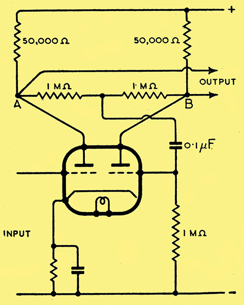
Fig. 4. Practical see-saw circuit employing a double triode valve.
In the February article the use of the triode and heptode parts of a frequency changer valve was shown.
Finally, the general relationship between voltage balance, valve amplification, and resistance ratio, of which we have so far considered only a few typical cases, can be worked out from Fig. 2 as follows.
Then
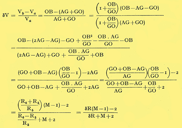
This result is in a form convenient for plotting curves showing how the voltage balance depends on the resistance balance and the valve amplification, as in Fig. 5, Where the 'out-of-balance' is given as a percentage of Va, for several values of M. When M approaches infinity, δR, 1 and 2 are relatively negligible, and the formula reduces to δV = δR. This is expressed by the dotted line.
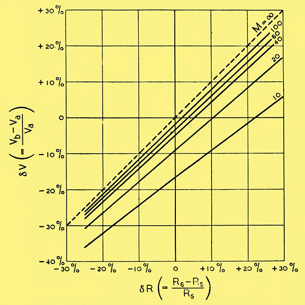
Fig. 5. Diagram showing the percentage departure from voltage balance (δV) in terms of the percentage difference between R6 and R5 (δR), for several values of amplification, M.
If R5 and R6 are assumed equal the unbalance can be read off the 'δR = 0' line. It is always negative (i.e., Vb less than Va) and is less than 10% provided that M is at least 20.
For perfect balance, δV = 0, so δR(M - 1) - 2 = 0; i.e., it is necessary to make δR = 2/(M - 1).
For comments on this article and the author's reply click here.
|