|
Various methods for adjusting the balance of a pair of triodes are considered. A new method is suggested which is based upon the adjustment of the cathode temperature so that the static anode currents are made equal. Measurements indicate that under these conditions the mutual conductance are then nearly equal, and the behaviour with respect to overall heater voltage changes is also improved.
In many applications, and particularly in the case of DC amplifiers, it is desirable to have a pair of identical valves. For example, in push-pull power output circuits this is necessary to obtain an exactly balanced push-pull output. In the case of DC amplifiers the pair of valves are arranged so that the effect of changes in supply voltages on the characteristic of one valve are compensated by changes in a similar, preferably identical, valve. Similarly, compensation is obtained for any change in the valve characteristics with time. Unfortunately, it is very difficult to obtain identical valves, particularly in the case of valves with an oxide cathode; and some means must be adopted in the associated circuits of adjusting for differences between pairs of valves.
Triode Parameters
The small signal parameters of a valve (for the sake of simplicity a triode is chosen, but similar arguments apply to pentodes at fixed screen voltage) which are of interest are the amplification factor (μ), the mutual conductance (gm), and the static anode current (Ia), all measured under fixed conditions, ie, heater voltage, anode voltage, and grid bias. (Note the dynamic anode resistance is μ/gm and is hence implied from a knowledge of it and gm). The static anode current is important, as it determines the static DC balance of balanced circuits, obviously of extreme importance in the case of DC amplifiers, although it is desirable from many points of view that the anode currents be equal in push-pull AC circuits - i.e., reduction of ripple, and of DC saturation of the output transformer.
If the parameters of a series of valves of the one type are measured it is found that μ shows small deviations of the order of a few per cent from the mean. The gm and Ia, on the other hand, deviate by well over ten per cent from the mean value. This is to be expected, as the amplification factor is, under ideal conditions, determined by the valve geometry, which with normal construction methods can be held to close tolerances, whereas the gm and Ia are also determined by the cathode emission, which is known to vary considerably in the case of oxide cathodes, even with the most carefully controlled production.
Balance Circuits
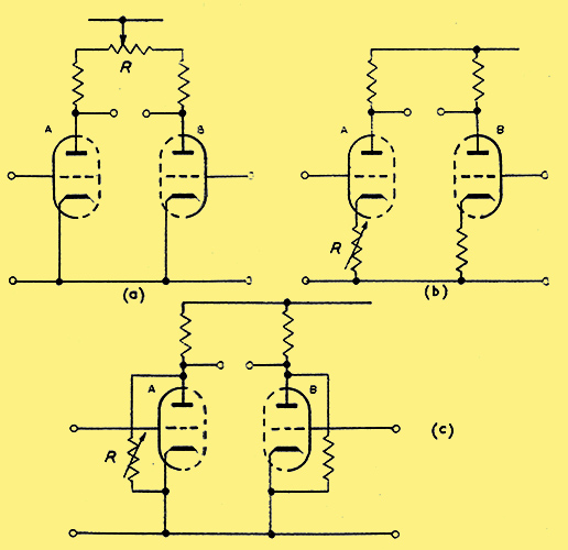
Fig. 1. Three basic methods used to balance the static properties of a pair of triodes.
In any double triode circuit it is possible to adjust for equality of either the static anode currents, the stage gain, or the effect of heater changes, but not for all three simultaneously. Normally, adjustments are made for equality of the static anode currents, or zero adjustment. Methods of doing this are shown in Fig. 1. For example, the anode supply may be taken through a potentiometer as in 1(a), and this adjusted for static balance. Alternatively, the bias can be changed as in 1(b) so as to give static balance. Finally, the valve may be shunted with a resistor as in 1(c). Unfortunately, if other adjustments are introduced so as to equalize also the stage gain and the effect of heater changes, the various adjustments are not independent, and in a multi-stage amplifier the use of three interacting controls on each stage would be impracticable.
More elaborate circuits have been devised to balance the anode current and the gain simultaneouslyb. However, these methods are based on the use of a large cathode resistance common to both valves, this serving to nearly balance the dynamic properties, and one of the methods of Fig. 1 is then used to balance the static currents. An example of this type of balance circuit is given in Fig. 2. However, this method is applicable only when using parallel balanced triodes with a large value of the common cathode resistor R, and hence is not applicable in many cases.
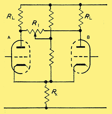
Fig. 2. A method for balancing both the static and dynamic properties of a pair of triodes.
New Balance Circuit
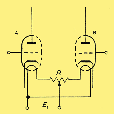
Fig. 3. New circuit for the overall balance of a pair of triodes
As the differences between triodes of the same type are mainly caused by differences in the emission from the cathode, it should be possible to balance valves by making the cathode emission the same. A new circuit4 based upon this fact is shown in Fig. 3. A potentiometer of a few ohms resistance is connected as shown so as to introduce a small difference ΔVh in the heater voltages of the valves 1 and 2. The simplest procedure is to adjust R so that the static anode currents of the valves are equal. If necessary, the overall heater supply can be increased slightly, but in many applications, for example in the case of DC amplifiers, it is desirable to run the heaters at a reduced voltage and the overall drop in R is not important.
It was found experimentally that the maximum difference in voltage between the two triodes amounted to 10 per cent of the normal for a batch of 50 twin triodes type 12AX7, and that of these approximately half could be balanced with heater voltage differences of only 5 per cent.
As the potentiometer R, is set so as to equalize the static anode currents, the valves will be perfectly balanced if the mutual conductances are equal and they respond equally to the effect of heater supply changes.
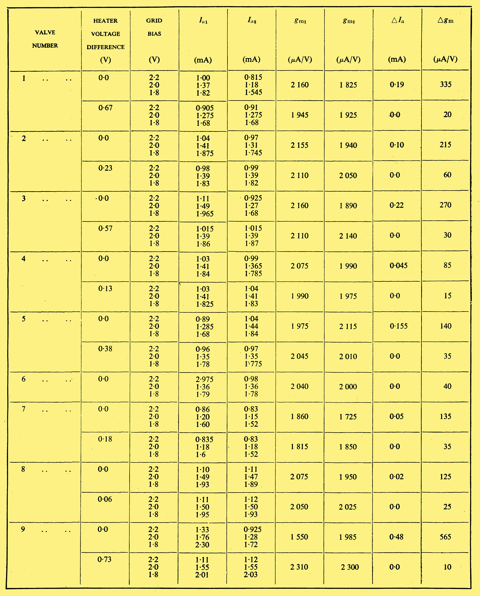
Table 1
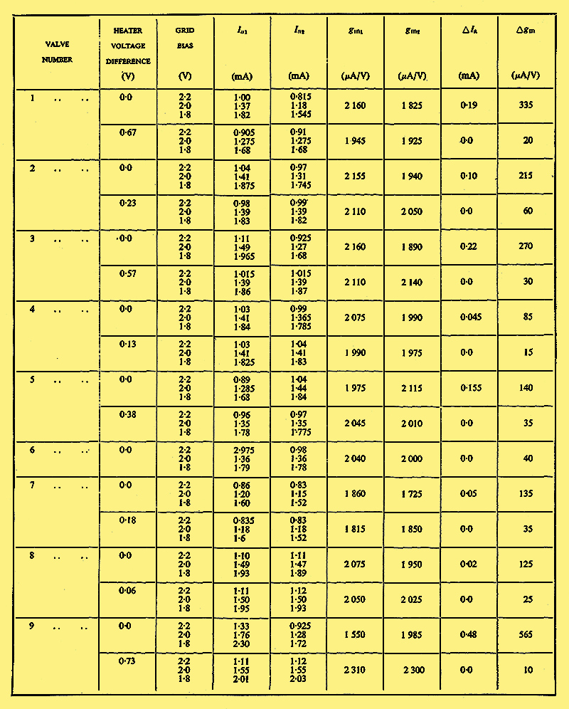
Differences Between Twin Triodes Before and After Balancing by Heater Compensation.
These two points were checked by measurements on a number of valves type 12AX7. Measurements on the mutual conductance are given in Table 1. The twin triode type l2AX7 was first tested at fixed heater voltage, then the heater voltages were adjusted for static balance at the recommended test conditions (anode voltage 250 V, grid bias -2.0 V). The dynamic balance was next measured by measuring the mutual conductance, and also the anode current at a grid bias of -2.2 V and -1.8 V. It is obvious that for all the valves tested the mutual conductances after balancing for Ia are almost identical. This would probably hold only for triodes of near-identical geometry, where the unbalance is caused solely by the differences in work function of the cathode. Once the emissions are made equal by adjustment of the cathode temperatures, the valves should then be identical apart from a slight difference in the escape voltage of the electrons from the cathodes. It is possible that the differences in temperature will introduce other side effects such as differences in life of the two triodes, different rates of poisoning, etc. However, balance adjustments are normally a routine adjustment in the case of DC amplifiers. The twin triode No. 1 of Table 1 was tested after 100 hours and the balance adjustment was found to have changed by 0.07 V, the new value of ΔVh being 0.06 V. It should be noted that out of the nine valves tested, one valve (No. 6) showed anode currents and mutual conductances to be nearly balanced without any further compensation.
Of major importance in DC amplifier design is the effect of heater supply variations, and several circuits are used to balance a pair of triodes for equality in changes due to heater supply changes2,3. Although the new circuit makes the cathode temperatures different, all other properties are nearly balanced, and to a first order it would be expected that the stability to heater supply variations would be also balanced.
Table 2
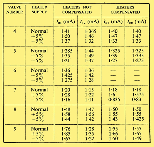
Measurements in Table 2 give the effect of a change of + and - 5 per cent on the overall heater supply. As is clear from these measurements, the compensation is good but not perfect. However, this result is typical of all heater compensation circuits, which rarely give an improvement of better than 20 :1 (Verhagen1).
Conclusions
It is concluded that the new balance circuit of Fig. 3 is capable of giving, simultaneously, an accurate balance of the static anode currents and mutual conductances of pairs of triodes. As the amplification factors are normally also balanced, this gives a pair of triodes, without selection, identical to within a few per cent. At the same time the balance with respect to overall heater supply changes is improved sufficiently to render heater compensation circuits unnecessary.
References
- Verhagen, C N A Survey of the Limits of AC Amplification. Proc. Inst. Radio Engrs. 41. 615 (1953).
- Miller, S E Sensitive DC Amplifier with AC Operation. Electronics 14, 27 (Nov. 1941)
- Artzt, M Survey of DC Amplifiers. Electronics 18, 112 (Aug. 1945)
- Aitchison, R E, A New Circuit for Balancing Pairs of Valves. Nature 174, 704 (1954)
|