|
The idea of using a cathode ray device for tuning indicators has been in the minds of designers for some time, for the bright fluorescent glow which can be obtained with modern screen materials is very suitable for giving a clear visual indication.
The 6E5
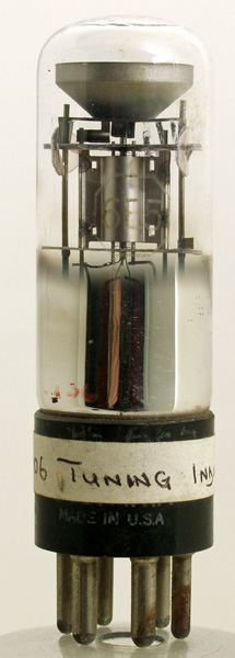
A particularly neat form of indicator has just made its appearance on the American market. The device, which is known as the 6E5 tube, is made in the form of a valve and fits a standard American UX6 socket. It provides a circular disc of light on which appears a wedge-shaped shadow which varies in thickness according to the value of the carrier, being broad under normal conditions but narrowing down to a thin line when full carrier voltage is applied.
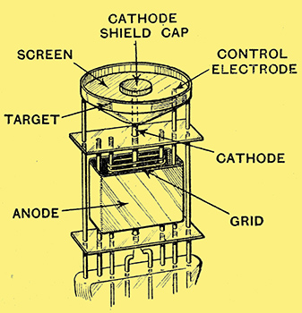
Fig. 1. - General construction of the 6E5 tube.
One of the difficulties with cathode ray equipment is that, if satisfactory brilliance is to be obtained, the control voltage is apt to be more than can conveniently be provided by any existing point in the receiver. This is overcome in the 6E5 tube by including in the device a valve which acts as a DC amplifier and thus delivers a magnified control voltage. In this way full operation is obtained off the normal AVC voltage developed in the set.
The construction of the tube is similar to that of a normal valve, except that the grid and anode only surround the bottom portion of the cathode, which extends through the top mica into the indicator portion proper.
Immediately over the top of the cathode is a circular fluorescent disc surrounded by a short cylindrical anode. Normally, therefore, the electrons attracted from the cathode by the positive potential on this auxiliary anode or target would hit the fluorescent screen in their passage, and cause it to glow more or less uniformly. The centre of the fluorescent screen is provided with a small cap which shields off the light from the hot cathode itself.
There is, however, an auxiliary electrode situated between the cathode and the target consisting of a short rod connected to the anode of the triode section. This rod is maintained at a potential a little lower than that of the target itself, and this repels the electrons in the neighbourhood of the rod. Consequently, the electrons are diverted in the region around the control electrode, so that a dark patch or shadow appears at one side.
Variation of Shadow Width
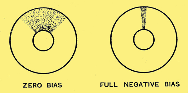
Fig. 3. - The shadow varies in thickness according to the value of the carrier.
The width of this shadow depends on the voltage on the control electrode. If this voltage is high, so that the electrode is nearly at the same potential as the target or main anode, the diversion of the electrons is small, and the shadow produced is in the form of a thin line. As the voltage on the control electrode becomes more negative relative to the target, an increasing number of electrons are deflected to the opposite side of the tube, giving a gradually broadening shadow. Due to the location of the control electrode, this shadow is wedge-shaped in form, as shown in Fig. 3.
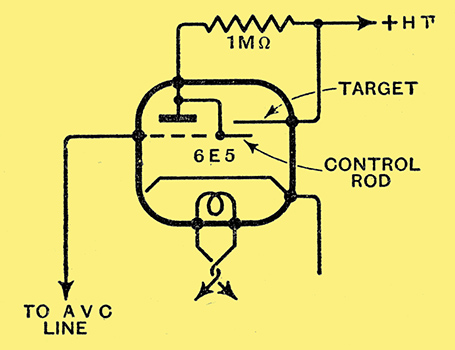
Fig. 2. - How the electrode connections are arranged.
The actual circuit is shown in Fig. 2. It will be seen that the control electrode is connected internally to the anode of the triode section. This obtains its voltage from the full HT (target) potential through a one-megohm resistance. The grid of the triode is connected to the AVC line so that normally the valve is only slightly negatively biased, causing an appreciable anode current flow and a correspondingly large voltage drop on the anode resistance. The control electrode is thus appreciably negative relative to the target, which results in a wide shadow.
As the AVC voltage increases, the grid of the valve runs negative, the anode current decreases, and the anode and control voltages rise rapidly, causing the shadow on the screen to become progressively narrower until it reaches the limiting position when the control electrode is practically at target potential.
Characteristic Curve

Fig. 4.- Characteristics of the tube.
Fig. 3 illustrates the type of indication obtained while the characteristics of the tube are shown in Fig. 4. The target current is practically constant at about 4.5 milliamps, being slightly less when the shadow is large, as one would expect. The anode current of the triode section is very small, in view of the high resistance through which the tube operates, and it is, of course, controlled by the grid bias in the normal way. The shadow angle varies between approximately 90 degrees and zero under normal conditions.
The scheme is an ingenious one, and the use of cathode ray streams for devices of this character may well play an increasing part in the technique of future radio receivers. It is possible, for example, to imagine relays constructed on this principle, and it may be that the 6E5 tube is the forerunner of a new class of thermionic device.
|