|
In response to numerous requests we are giving full details for the easy conversion of an ordinary set so that it can take one of those wonderful screened-grid valves. The example chosen uses a very popular type of circuit.
Have you ever considered the possibility of using an SG valve in place of the present valve in the HF stage of your receiver, and do you know what alterations are necessary to the circuit in order to make this possible?
Perhaps, are even wondering why it should be necessary to have to make alterations at all when it is desired to change over to a screened-grid valve.
Preventing Feedback
In these circumstances it is reasonable to suppose that a few words of explanation will not be altogether amiss, although it should perhaps be explained that the main object of the present article is to deal with the practical, rather than with the theoretical, side of the question, and that in consequence the 'theory' part of the business must be kept short.
When designing the HF stage of a set on the ordinary neutralised principle, the coils, wiring, etc., are so arranged that as far as possible no coupling shall take place when the set is working between the grid and anode circuits of the HF valve.
The distance separating the coils is based to a large extent upon the degree of amplification given by the valve, since the strength of the 'fields' round the coils is very largely governed by this factor. The SG type of HF valve differs from the ordinary variety in that it has a very much higher amplification factor although, of course, this is not the only essential difference between the two valves.
Consequently, when an SG valve is used replace a valve of the ordinary HF type a set, the coil 'fields' increase due to the much greater degree of amplification given by the SG valve, and as a result, there is a danger of the set becoming unstable through coupling effects.
Alterations Essential
Quite apart from the question of coils, there are, of course, other contributory reasons for the tendency towards instability, such as, for instance, coupling between the wiring. Thus, in point of fact, there are very few sets with ordinary neutralised HF stages into which an SG valve can be placed, without in some way modifying the existing layout and arrangement.
In attempting to deal with the practical side, one is faced with the difficulty that there are literally dozens of different ways in which to couple the valve to the detector, although I do not think there is very much doubt as to the arrangement most generally in use.
It is obviously quite impossible in the scope of a single article to give directions which will be applicable to all receivers, and since, to deal with the subject at all thoroughly, it will be necessary to limit the subject to one particular type of set, I propose to deal with those employing the popular split-primary-transformer method.
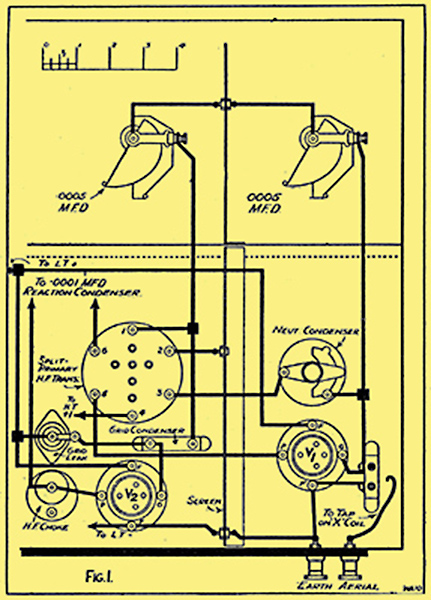
Fig. 1. The HF side of a set employing a straight forward circuit, which can be modified quite easily to accommodate a screened-grid valve.
The HF side of a typical set employing the split primary-transformer scheme is shown in Fig. 1, and although in this particular example a coil of the plug-in 'X' type is shown in the grid circuit of the HF valve, it is quite feasible that in many sets the grid coil will be one of the six-pin variety or possibly even two separate plug-in coils.
The actual method of aerial coupling is quite immaterial, and the part of the circuit with which we are most concerned is that associated with the anode circuit of the HF valve, in other words, the split-primary transformer.
The Best Way
Perhaps the most helpful way in which to deal with the subject of alterations would be by mentioning as a start the components it is necessary to remove. I use the plural, although, as a matter of fact, there is only one which has to be removed entirely, and that is the neutralising condenser.
In order to carry out the alterations you will require in addition to the screened-grid valve one HF choke (a good quality choke is strongly to be recommended for use here), one 0.001 μF fixed condenser, two 0.25 μF Mansbridge condensers and two more terminals.
Not Difficult
These components are all mounted in position to the right of the vertical screen, and since there is nothing particularly complicated in this part of the work, there is not much point in going over what is already shown quite clearly in the diagram (Fig. 2).
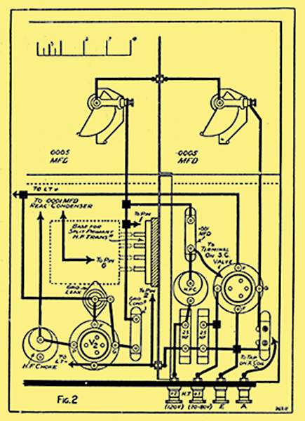
Fig, 2. Here is a diagram showing how the new connections run.
The portion of the set to the left of the vertical screen, however, is not quite so straightforward, although as far as the wiring is concerned this part of the circuit will be even more simple than it was before. The HF transformer in its present position is not satisfactory, and if left as it is would in all probability produce instability. If, however, you do not particularly wish to move the six-pin base, it can be left where it is, providing, instead of the present six-pin split-primary transformer, you use a binocular coil of the same type.
I expect, however, that most of you will desire to use up your existing components in preference to purchasing new ones, and it will therefore be necessary for you to mount the six-pin base against the side of the screen. For this purpose the best plan is first to mount against the screen a piece of wood, and it then becomes a simple matter to fix the six-pin base in position..
Full details of the wiring alterations involved are clearly shown in Fig. 2, and perhaps I need only mention that the pins 3, 4 and 5 on the six-pin base are not now used.
New HT Voltages
When the wiring alterations have been completed, it only remains to put the SG valve in the first holder, and to connect to the top of the valve the flex connection, from the 0.001 μF condenser. With regard to the new HT plus terminals, the one on the right (marked + 1) should be joined to a position on the existing HT battery at about 70 or 80 Volts, and the other terminal requires about 120 Volts (also from the same HT battery). If a separate HT plus terminal was used for supplying the HF valve in the original set, only one new terminal will, of course, be necessary.
|