|
How electron lenses are arranged in cathode-ray tubes.
Cathode rays are streams of electrons in a vacuum. Each electron conforms very closely to Newtons laws of motion; that is to say, so long as it is not acted upon by any force it stays where it is or moves at constant speed in a straight line, and when a force acts on it in any direction it accelerates in that direction at a rate proportional to the force. An electron is so light that the force of gravity on it is negligible, but it responds smartly to electric and magnetic fields. An electric field is usually measured in volts per metre (or cm), and an electron placed in such a field accelerates positive-wards along the imaginary lines of electric force. These lines are at right angles to the equipotential lines, i.e., lines joining all points at the same potential. If the electric field is curved, or the electron already has some velocity in a different direction, its track does not coincide with any line of force, but bends in towards it as the acceleration in that direction increases; just as a ball thrown out of a top-floor window does not immediately follow the lines of gravitational force downwards but curves gradually towards that direction. Consequently an electrons track can be bent more sharply by a given electric field when the electron is travelling slowly than when it is fast. Its speed depends on the field strength multiplied by the distance through which it has acted, and this product is the total potential difference; if it is denoted by V volts the speed reached by the electron from a standing start is 593 √V kilometres per second. The track of an electron in a given electric field pattern can be calculated from these principles, but the practical problem, which is the reverse - to find the shapes and voltages of. electrodes needed to produce a field pattern that will make the electrons in a cathode ray follow a desired pattern of tracks - is more difficult, and is largely a matter of cut and try. A help towards visualizing the relationship between electric field patterns and electron tracks is the analogy in which electrons are represented by little balls, electric field by gravity, intensity of field by gradient of the surface along which the balls roll, p.d. by difference in height, and equipotential lines by contour lines.
The problem in any cathode-ray tube is to persuade the electrons, which tend to fly off in all directions by mutual repulsion, to converge to a particular point somewhere on the fluorescent screen. If they were sent towards this point slowly, their mutual repulsion would again have time to work and they could not be crowded together to produce a sufficiently small and intense spot. But if they are shot towards it at many thousands of miles per second they are there before they have time to realize that they hate one anothers faces. So that is why a high voltage is applied between cathode and anode - which is sometimes very appropriately called the accelerator.
The converging, or focusing, can be done by either electric or magnetic fields, or of course both. In most oscilloscope tubes focusing is done by electric fields. In most television tubes it is done magnetically, but there is a tendency now to revert to electric focusing in order to save the cost of the magnet. Before we tackle a complete CRT it may help to clarify our mental pictures if we review the simple process of making a broad stream of marbles converge towards a point.
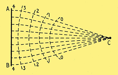
Fig. 1. Contour map of a valley slope (Fig. 2) for making marbles roll from AB to C. The numbers attached to the contour lines are in inches above C level. The other dotted lines are the tracks of the marbles: note that by the time they have reached the last (zero) contour their momentum prevents them from rolling down exactly at right angles to the contour lines.
Suppose they are being delivered uniformly along the front AB in Fig. 1 and that we want them to arrive at C. To get them moving in that direction it is of course necessary to make the surface slope down towards it. The speed they develop (friction neglected) is 8 √H, where H is the total height in feet they lose in the process; this formula is analogous to 593 √V for electrons. To obtain, in addition, convergence towards C the obvious method is to channel the slope into a sort of valley. The marbles respond best to this treatment near the start, before they have got up enough speed for their momentum to have much effect. Once their tracks have been directed towards C, it doesnt matter if the rest of the ground is flat.
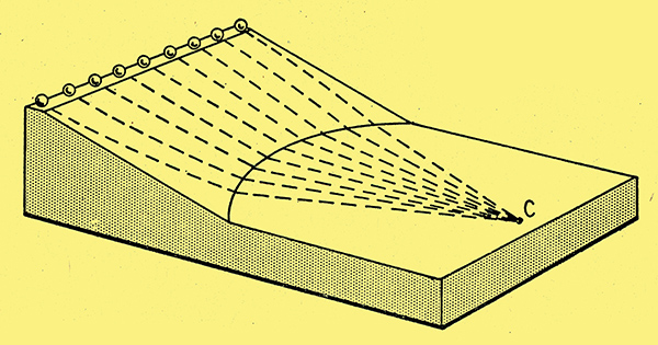
Fig. 2. Model, of which Fig. 1 is the contour map. An electric field having equipotential lines of the same pattern as the contour lines of the model would make electrons follow similar tracks.
One procedure would be to make a model as in Fig. 2 and vary the shape of the channel until the balls actually did all arrive at C. Fig. 1 could then be derived from it, as a contour map of the model, the numbers on the contour lines being 'inches above C level'. Note that at first the tracks are almost at right angles to the contour, but nearer the foot the marbles momentum makes them swing out slightly.
Alternatively, if one were better at maths than at modelling, the contour lines required to obtain the converging tracks could be calculated and plotted as in Fig. 1, and these contour lines used to form an experimental model as in Fig. 2, by which the calculation could be checked. If now an electrode system were designed to produce equipotential lines shaped exactly like the contour lines in Fig. 1, electrons released along AB ought to converge on C, provided that their speed was sufficient for their mutual repulsion to be negligible. Of course the potentials of the equipotential lines must be proportional to minus the heights of the contours.
Gravity models have actually been used in the practical development of electron lenses, but a more usual device is the electrolytic tank.
Typical Focusing System
Let us now follow the evolution of a typical electric focusing system or lens in a CRT. To show what happens in the small holes through which the beam passes it is necessary to draw these parts larger than life, and if the whole tube were drawn on the same scale - well, the Editor would disapprove! So the diagrams that follow, which are longitudinal sections, are not accurately to scale.
The first requirement in the vacuum tube is a heated cathode, for emitting the electrons; and next, an anode for accelerating them in the desired direction. If the anode were simply a plate, the electrons would all crash into it and there would be no beam to light up the screen. So a hole is made in the centre of the anode, as in Fig. 3.
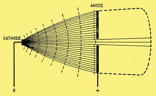
Fig. 3. Equipotential lines (dotted) and electron tracks in a tube having only a cathode and perforated anode. The space enclosed by the dotted boundary on the right is supposed to be all at the same potential as the anode.
Removing this bit of metal does not much affect the potential of the space it leaves, for that space is surrounded by metal at the anode potential. So electrons starting off from the cathode scarcely notice the difference. As we saw last month, the equipotential lines are closer together where the lines of force diverge from a relatively small electrode, which means that the electrical slope is steepest near the start, and the electrons accelerate very rapidly.
Electrons right on the axis go clean through the hole, for although the anode attraction becomes increasingly sideways as they approach it, the sideways pulls are equal all round and cancel out. Even electrons slightly off the axis are traveling so fast by the time they are near the hole that only those very close to the edge would be deflected sufficiently to hit the anode. In Fig. 3 a contour line has been drawn very close to the anode to show how the field tends to follow the shape of the anode into the hole. The tendency for the electron tracks to be attracted towards the lines of force at right-angles to this line is small, and does little more than cause the beam that goes through the hole to spread out slightly. To prevent it from being spread out more by positive surroundings beyond the anode, or being repelled back to the anode by negative surroundings, the space beyond the anode is kept at or near anode potential so that the electrons that get through continue on in straight lines.
An obvious disadvantage of the system so far is that most of the electrons go to waste by colliding with the anode, leaving only a feeble beam to light the screen. One step towards remedying this is to start the electrons off on the right lines by making them run the gauntlet of a negatively charged cylinder, as in Fig. 4.
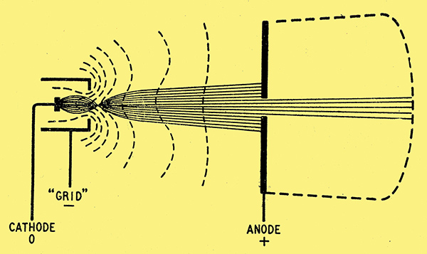
Fig. 4. The addition of a cylindrical control electrode ('grid') at a slightly negative potential provides a more highly concentrated and controllable electron beam.
If this is made too negative it neutralizes the strong but distant attraction of the anode and prevents any electrons from getting out, so it serves the double purpose of beam-forming and controlling the amount of beam current, and by analogy with a valve (rather than any physical resemblance) is usually called the grid. One of its effects is to focus the beam at a point just beyond where the beam emerges from the grid. In a well-designed tube the diameter of the beam at this point (called the cross-over) is smaller than the emitting surface of the cathode, so in effect the electrons are coming from a close approximation to the ideal point source, to the benefit of subsequent focusing.
If the screen were just beyond the anode the spot of light would be little bigger than the hole in the anode. But to leave room for deflecting the beam over a reasonable area the screen has to be a considerable distance beyond the anode, and even if the hole were extremely small the beam would spread too much to give fine definition, and, moreover (having come through such a small hole) it would be very weak. So the hole is made relatively large and the wide beam going through it is made to converge. The arrangement that does this is the electrons lens proper. There are innumerable varieties, but many of them comprise three anodes; in some, these anodes are kept at progressively higher potentials; in others, the first and third are highly positive and the second is less so, or even at or near cathode potential.
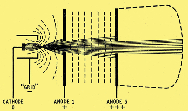
Fig. 5. Although the addition of another disk anode at a higher potential does not improve the focusing it is a step towards an effective electron lens - Fig. 6.
Fig. 5 shows the sort of thing that would happen if the first and third anodes were disks with relatively large holes and the middle anode were omitted. The field between the anodes would be fairly uniform and would accelerate the beam but have little or no focusing effect.
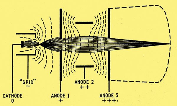
Fig. 6. An intermediate anode of cylindrical shape bends the equipotential lines (which are actually sections of equipotential surfaces) as here, making the beam converge to a point on the fluorescent screen.
Now put in a middle anode of cylindrical shape, as in Fig. 6. The metal wall of the cylinder short-circuits the electric field, for obviously it is all at the same potential, and so the equipotential lines are crowded together at the edges of the cylinder but are free to spread out in the centre. Remembering that the electrons tend to take the shortest cut from one equipotential line to another (but at the speed they are now doing they only tend to do so) we see that this pattern will make them converge. If it is found that the point to which they converge is, say, short of the screen, then by raising the potential of the middle anode some of the equipotential lines are transferred from the converging region to the diverging region, and the point of convergence is pushed farther away from the lens. This adjustment alone does not ensure that all rays converge on the same point to give a sharp focus; that depends to some extent on the voltages applied to the other anodes, but mainly on the shapes of all the anodes.
Reversing Potential Gradient
A system basically like that just described is quite usual in oscilloscope tubes. The requirements for television are more exacting, and in a recent design there are four anodes: the first at only about +250 V, to attract the electrons gently through the grid orifice; the second and fourth forming a long cylinder with one section removed; and the third, between them, at about zero volts. The second and fourth are at about +10,000 V. One important thing to note about this and many other electric lenses is that the potential gradient reverses (in this example between the second and third anodes). After having fallen rapidly down a steep slope, the electrons have to go uphill for a short distance, like a switchback. If they strike this upward slope head-on, at right angles to the equipotential lines, all that happens is that they are decelerated. The final velocity corresponds to the net difference of potential between start and finish. But if they strike the upward slope at an angle, that angle is increased by the slope (instead of being diminished, as it would be if the slope were downward). One can easily check this by rolling balls up a slope. Of course, if the slope rises to a greater height than the original starting point, it fails to clear the summit and rolls back; but in the electron lens with the zero potential third anode this condition is avoided by placing it so that it is largely screened by the 10 kV anodes.
I hope that by the time of the next Radio Show someone will have made a gravitational model for the educational stand. A better method than messing around with plaster of Paris is to mount a sheet of rubber in a horizontal frame and clamp portions of it (corresponding to sections of electrodes) at heights representing the potentials of those electrodes. It could be a simple matter for the heights to be variable, showing the effects of focusing adjustments and also of deflecting potentials, about which I have said nothing, because their principle ought by now to be obvious.
Of course, it must be realized that although such a model is three-dimensional. it represents the electric field pattern in only two dimensions - a cross-section of the electron lens, as in Figs. 1-6 here. The lens is (or should be) symmetrical around its axis, so that the same diagrams or models hold good for all longitudinal sections. Equipotentials are always surfaces; it is only in section that they appear as lines.
The reason why this three-dimensional situation can be discussed on two-dimensional paper is that the direction in which electrons are accelerated by an electric field is the same as the direction of the field (lines of force). And the reason why the effects of magnetic fields are so much more difficult to visualize is that the direction of acceleration is at right angles both to the direction of the electrons movement and the direction of the field, so even when the problem is presented in its simplest form it still involves three dimensions. And in a solemn session of the Institution of Electrical Engineers I once heard one learned gentleman after another confess that visualizing anything in three dimensions was quite a headache. (Viewers of 3D films will doubtless heartily agree.) However, it is a difficulty that is basic to electro-magnetism. In ordinary electrical engineering - dynamos, motors, etc. - the problem is often a little easier because the electrons are confined to conductors, which are usually not free to move just anywhere. Electrons in a vacuum are not so bound. Their gyrations under the influence of combined electric and magnetic fields are the mathematicians delight - but the non-mathematicians. despair.
However. Suppose we start with an electron gun something like that shown in Fig. 4, but with a larger hole, through which a slightly diverging beam of electrons is shot at high speed towards the screen. And suppose now that we wind a long coil around the beam, as in Fig. 7, producing a magnetic field pointing the same way as the electrons. What happens?
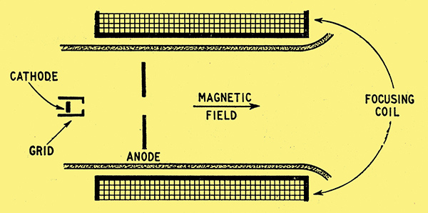
Fig. 7. Section of electron gun, surrounded by a long coil designed to produce a nearly uniform magnetic field down the tube in the same direction as the electron beam.
To those electrons right at the centre of the beam, along its axis, nothing; for their path coincides exactly with the axial magnetic line of force, so they do not cut across the field, even slightly. So far as they are concerned there might not be a field. But those that are diverging do cut across the field, and so come under the law that makes electric motors motor. The appropriate memory-aider is the Left Hand Rule: if the thumb and first two fingers are stuck out all at right angles to one another, and the First finger is pointed in the direction of the magnetic Flux, and the second finger in the direction of the Current (which is opposite to the direction of the electrons) across the flux, the thumb shows the direction in which the electrons tend to move because of the electromagnetic force.
Cathodes-eye View
Now in our CRT the movement of the electrons, in so far as it is straight down the tube, parallel to its axis, is not across the flux at all, so merely confuses the issue; the proper viewpoint for seeing the movement across the flux without the axial movement is from the cathode. So here, Fig. 8, is a cathodes eye view of the electron beam.
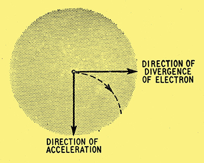
Fig. 8. Cathodes-eye view of the beam, showing the effect of the magnetic field on an electron diverging to the right.
Electrons along the axis remain at the centre all the time so do not appear to be moving at all; all others appear to be radiating outwards. Let us fix our attention on one particular electron just leaving the cross-over and diverging to the right. Since, for purposes of the left-hand rule, that is equivalent to a current in the opposite direction, the second finger should point to the left. The forefinger is pointing away, along the flux line, so the thumb shows that the force acting on the electron will make it accelerate downwards. If for simplicity we assumed (what in a real tube is not likely to be true) that the speed of divergence was constant, and also (what is certainly not true) that the direction of acceleration continued to be downwards, then the path of the electron would. be a curve as shown dotted. This is the same kind of curve as that traced by a ball thrown horizontally, and for the same reason - that the ball is given a constant speed horizontally, combined with a steadily growing speed downwards. In practice, during the first stage of the electrons flight, from cross-over to anode, it is not going at uniform speed but is being accelerated by an electric field; it is only from the anode onwards that its horizontal motion is at constant speed. However, this complication is largely offset by the fact that the electromagnetic force causing the electron to accelerate downward is proportional to the speed of the electron as well as to the strength of the magnetic field. The real complication is the second one - that the downward acceleration doesnt keep on being downward. It is always at right angles to the electron, so directly the electron starts curving downward as in Fig. 8 the magnetic acceleration veers round to the leftwards. This makes the electron curve all the quicker, which keeps the acceleration veering, and so on. When the ordinary mind tries to follow the electron it is therefore likely to become very dizzy. Even the chap who rather fancies his proficiency with the calculus and tackles the thing mathematically may quite possibly get himself into a mess.
But the situation is exactly similar to a very familiar one - a weight being whirled round at the end of a string, or, if you prefer, the earth revolving round the sun. The weight, let us suppose, is given a constant speed in a certain direction - say the original direction of the electron in Fig. 8. But being attached to the string it cannot go out in a straight line; it goes round in a circle centred at the point where the other end of the string is fixed. To keep it in this orbit, the string has to exert a tensional force. This force is obviously always at right angles to the direction the weight is going. And if the speed of the weight is constant, so too is the force. Since these are exactly the conditions that govern the movement of the electron, it is reasonable to suppose (and it can be confirmed mathematically) that the electron whirls round in a circle.
Corkscrew Electron Tracks
All electrons have the same mass and charge, and we are assuming that the magnetic field is the same for all, so for a given speed they all experience the same force. Actually, of course, the speeds with which they cross the field are different; those only just off the axis diverge much more slowly than those on the outside of the beam. But if the equation for centrifugal force is applied to weights that are all the same, and force proportional to speed, it shows that the time for one complete revolution is the same for all, regardless of speed. The faster speeds are handicapped by having to take bigger circles. The same applies to electrons. So after a certain time all electrons that started off from the centre together, whether fast or slow, have done one revolution and arrive back on the axis again simultaneously. In the meantime, of course, they have been travelling down the tube, so the electron tracks are actually like a corkscrew - or a helix, to be more scientific.
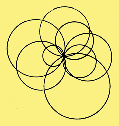
Fig. 9. The divergent paths of electrons, as seen from the cathode, are curled round into circles by the magnetic field. The time taken to do a complete circle is the same for all electrons, slow or fast.
Fig. 9 shows one curl each of a few electron tracks as seen from the cathode. The small circles are made by slowly diverging electrons; the larger circles by the faster ones.
Increasing the strength of the magnetic field increases the centre-wards force on all the electrons, so tightens their curls and reduces the time they take to execute each complete turn. To get a well-focused spot it is obvious that the strength of the magnet must be adjusted so that one of the times when all the electrons meet again is the moment they reach the fluorescent screen - which is a grand place for a reunion; they all get beautifully lit up.
Obvious it may be, but quite unpractical. To keep the electrons corkscrewing all the way to the screen it would be necessary to maintain the uniform magnetic field all the way there - a point that seems to have been overlooked in some of the drawings I have seen, purporting to explain magnetic focusing. Even to provide a magnet as long as the one in Fig. 7, extending as far as where the tube begins to open out, is too expensive and inconvenient, let alone one enveloping the entire tube, screen and all! So in practice a very short magnet is used, producing a curved field pattern something like Fig. 10.
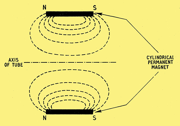
Fig. 10. In practice a short magnet is used, and the effect on the electrons is more complicated.
If you have been thinking that the theory of magnetic focusing has already been complicated enough, even with our beautifully uniform but quite unpractical field, you (and I) may well quail at the prospect of having to trace precisely what happens to diverging electrons in a field that varies rapidly both in strength. and direction. But the operative word is 'precisely'. We can make a guess at roughly-what happens.
At first, before an electron gets into the magnetic field, it is diverging quite happily in a straight line. But before it has had time to go too far, at the comparatively slow speed of this first stage of the journey, it finds itself going through the magnet ring, with a strong magnetic pull making it wheel round sharply. The magnet has been made of such a strength that by the time the electron is beyond its influence it has done an about-turn and is converging towards the axis again, as in the view from the cathode in Fig. 11.
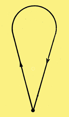
Fig. 11. One effect of shortening the magnet is to change the circles of Fig. 9 into shapes more like this. The final result can still be satisfactory, and much more conveniently obtained.
But dont ask me to produce a mechanical analogy to demonstrate all this! The proof of the thing is on your TV screen.
See also Electrons in Picture Tubes.
|