|
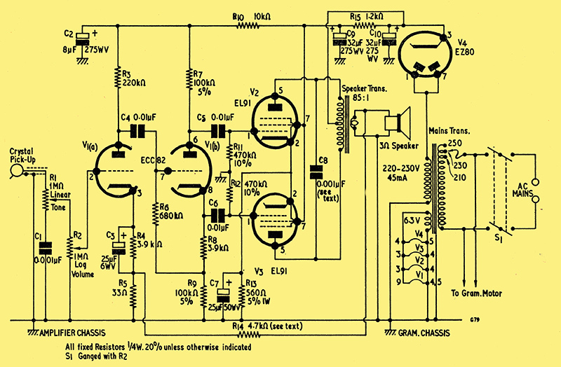
The complete circuit of the EL91 based Amplifier.
The amplifier described here was Suggested Circuit 148 - Push-Pull Record Player Amplifier with Isolated Chassis. An initial discussion of the advantages of an isolated chassis over an AC/DC circuit have been omitted due to the lethal problems with a direct mains connection to the chassis if connected incorrectly.
Having concluded that a mains transformer was inevitable if the aims of the design were to be met, the next design step consisted of finding a compromise between the cost of the transformer and the HT consumption in the amplifier. The most inexpensive type of isolating mains transformer generally available to the home-constructor is of the type having a half-wave (ie not centre-tapped) HT secondary, and the maximum current rating available here is 45mA. This is a total HT requirement of 11.4 Watts. After studying the capabilities of different output stage combinations, it was decided that an amplifier having quite an acceptable performance could be operated at this HT current. In consequence, the design described this month employs an isolating mains transformer with a 45mA half-wave secondary. See also A valve amplifier for the study where this EL91 design is driven by an old laptop 15 Volt supply.
The Amplifier Design
The first requirement of the amplifier associated with the mains transformer just discussed is that it should give greater gain and less distortion than a single pentode circuit. The most obvious and effective method of reducing distortion is to change from a single-ended output stage to a push-pull stage, whereupon the major question which has to be settled is the economic choice of valves which meet the 45mA HT current limitation.
What, at first sight, appear to be the most economical solutions are to employ two triode-pentodes, or a double-triode followed by the Brimar double-pentode type ELL80. In the first instance, one triode of one triode-pentode would function as a voltage amplifier, the triode of the second triode-pentode would operate as a phase-splitter, and the two remaining pentodes would make up the push-pull output stage. In the second instance, the double-triode would provide the voltage amplifier and phase-splitter, and the ELL80 the output stage. Unfortunately, the triode-pentodes generally available (with one exception), together with the ELL80, all require an HT consumption in excess of 45mA. The triode-pentode which could meet the 45mA requirement is the ECL80, but this has the disadvantage of having a common cathode for both triode and pentode sections. The common cathode would make the provision of a simple amplifier circuit, as envisaged here, somewhat difficult.
The alternative choice is to employ two separate pentodes having the requisite HT current consumption in the push-pull output stage, these being preceded by a double-triode voltage amplifier and phase-splitter. This choice was adopted, and the valves finally chosen by the writer were an ECC82 for the double-triode and two EL91s for the output stage. In the circuit employed here, the latter would offer some 4 Watts of audio power, which should be quite adequate for record player requirements. Despite the fact that three valves are now envisaged, instead of two (i.e. two triode-pentodes, or a double-triode and an ELL80), costs are still low. At the time of writing both the ECC82 and EL91 are advertised in this journal at five shillings each. (Incidentally, the EZ80, employed as the HT rectifier, is similarly listed at six shillings.)
The Circuit
The complete circuit of the amplifier is illustrated above. In this diagram the output of the crystal pick-up is applied to the tone control circuit given by R1 and C1. When the slider of R1 is at the lower end of its track, C1 causes attenuation of the higher frequencies whilst, with the slider at the top of the track, C1 has negligible effect. R1 functions, in consequence, as a top-cut tone control.
The audio from R1 is applied to the volume control R2 and, thence, to the grid of the voltage amplifier V1(a). V1(a) amplifies in conventional manner, its output/being applied to the phase-splitter V1(b). Audio frequency voltages of opposing phase appear at the anode and cathode of V1(b) and are applied, via C5 and C6, to the grids of V2 and V3. These two valves form the push-pull output stage and their anodes connect to the primary winding of the speaker transformer. A small degree of negative feedback is taken from the secondary of the speaker transformer, and is applied to the cathode of V1(a) by way of R14 and R5. An EZ80 is used as HT rectifier, its anodes being strapped and connected to the half-wave HT secondary winding of the transformer. The cathode couples to the reservoir capacitor C10, this being followed by the smoothing components R15, C9 and R10, C2. The output valve anodes take their HT supply from the reservoir capacitor, whilst their screen-grids are fed from the voltage across C9. V1(a) and (b) operate from the HT voltage across C2. The method of connection employed in the HT circuit allows resistance-capacitance smoothing to be used without the necessity for high wattage ratings in the resistors.
The 6.3 volt secondary winding of the mains transformer has one side connected to chassis and feeds all heaters, including that of the rectifier. The 1.3 Amp figure indicated in the circuit diagram represents the minimum current rating required in this winding.
Points of Design
The circuit is extremely simple and straightforward and should offer little trouble in practice. Nevertheless, there are some points of design which require a little further comment. It will, for instance, be noted that no limiter resistor is connected in series with the rectifier and the reservoir circuit. In practice, the required limiting resistance will almost certainly be given by losses in the mains transformer. The EZ80 requires a limiting resistance of 125 Ω per anode when employed as a full-wave rectifier with a 250-0-250 Volt input. If, in the present instance, the resistance of the HT secondary, plus that of the primary, exceeds 125Ω (as it very probably will), the rectifier can be assumed to be working under safe conditions. Should it happen that the sum of primary and secondary resistances falls below 125Ω, a physical resistor to make up the value could be inserted between the secondary winding and the anodes. The constructor should check the resistances of the HT secondary and primary windings of the particular mains transformer employed to ensure that the limiting resistance requirement is met before constructing the amplifier.
Capacitor C8, connected across the primary of the speaker transformer, offers a degree of top-cut. This capacitor appears inside the feedback loop, a fact which would not occur in a more expensive, true high fidelity, design. However, capacitors of this nature appear in the same circuit position in a number of push-pull commercial record player and radiogram designs and, for low feedback levels, help in achieving the desired frequency response. High AF voltages are liable to appear across C8, and it might be advisable to employ a capacitor with a working voltage of 500 because of this. It is possible, according to the speaker and speaker transformer employed, that better results will be given if the value shown for C8 is increased or decreased, and this point may be determined by experiment. Smoother top-cut would be given if an additional 10kΩ resistor were connected in series with C8.
The speaker transformer should have a ratio (between the whole primary winding and secondary) of 85:1. This corresponds to an anode-to-anode load of 22kΩ. The anode current in each half of the primary is of the order of 20mA and so (from the point of view of cost) a small transformer may be employed.
The cathode bias resistor, R13, is given a value of 560Ω at 5%. This close tolerance is desirable because R13 controls the HT current drawn by the output pentodes. With the resistor value specified, this current can closely approach the 45mA available from the transformer.
Construction
Few problems should be incurred during construction as, due to its inherent simplicity, the amplifier should prove to be quite stable. Obviously, a logical layout should be used, with the input circuit well removed from the output valves and power circuits. The gain offered is of the same order as a conventional triode-pentode audio amplifier, and there will probably be little point in using bus-bar earth returns in the amplifier chassis. Earth returns to the nearest chassis point should be quite adequate. On the other hand, it would be advisable to use a common earth point on the amplifier chassis for the connections to the pick-up screening and the bonding lead to the gram motor deck. The pick-up screening should be insulated from the metalwork at the deck itself.
Initial construction should be carried out with R14 disconnected. When completed , the amplifier should work adequately without this resistor, although gain may be a little excessive. The resistor may then be connected into circuit, whereupon gain should be reduced and output quality perceptibility improved. If R14 causes the amplifier to break into violent oscillation, the connections at the speaker transformer secondary should be reversed. The value specified for R14 should prove adequate for most amplifiers and speaker transformers encountered, and should not result in oscillation due to excessive phase shifts in the latter. If desired, a lower value could be employed, provided it does not cause instability. The lower value will then result in increased feedback.
It is possible that the output from some pick-ups will be higher than is required for the amplifier. If this occurs, a simple fixed potentiometer may be added before R1, as shown below.
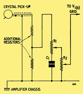
The sum of the two resistors employed in the potentiometer should be between 1 and 1.5MΩ, and the amount of attenuation which is given depends upon the ratio between the lower resistor and the total resistance.
If trouble is experienced with mains modulation, this should usually be cleared by reversing the connections at the mains plug. It may also prove helpful, in this respect, to reverse the connections to the gram motor. Because of the use of an isolating transformer, the amplifier and gram chassis can, of course, be earthed.
It should be possible to build the amplifier on a small chassis capable of being installed in most record player cabinets. Careful attention should be paid to cooling, and adequate ventilation apertures should be provided. This point applies especially to the mains transformer, which will be operating at or near its full rated HT output.
|