|
The users of DC radio receivers and radiograms have always been at a disadvantage with their AC brethren by reason of the limitation imposed by the voltage of their supply mains. The nominal voltage of DC mains ranges between 200 and 250, according to localities, giving an average supply voltage of 225, and this is further reduced by the subtraction of the bias for the valves and HT smoothing.
To obtain the maximum power output from the receiver at this voltage a pentode output valve is usually used, owing to its sensitivity and to the low bias voltage required. At the same time, however, it is generally conceded that the pentode requires a great deal more care in the design of the associated circuit and components than is the case with the triode. In particular, the output transformer must be carefully chosen if the upper musical frequencies are to be reproduced naturally and the load impedance has a critical value for minimum distortion.
The substitution of a triode for the pentode, while reducing the sensitivity of the output stage, leads to more faithful response without critical adjustments, and the valve is more good tempered under varying circuit conditions.
The conventional output triode for AC circuits employs a directly heated cathode, the bias being obtained from a resistance inserted in the lead to the centre tap of the heating transformer. With a valve intended tor use on DC, of course, this is not possible, and the advantages and stability of a self-bias circuit can only be obtained with an indirectly heated cathode. The alternative of separate battery bias need not be seriously considered, as the deterioration and frequent adjustment of such an arrangement detract from the smooth running of the all-mains set.
In changing the design of the output valve from direct to indirect heating a corresponding modification in the characteristics is unavoidable. With the directly heated filament the lower bend of the grid Volts v anode-current curve is sharper owing to the fact that it obeys a 5/2 power law. Indirect heating results in a longer tail to the curve which approximates more to a lower power law. The difference is slight but is nevertheless noticeable on comparison, and necessitates the use of working point higher up the curve than would be the case in a directly heated output valve.
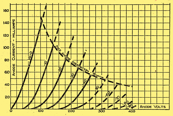
Fig. 1.-The anode Volts v anode-current characteristics of the PP3521 valve.
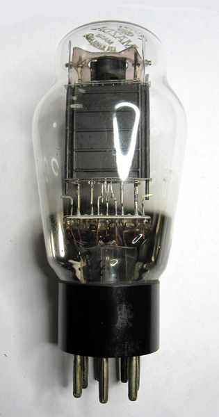
The Mazda PP3521, of which the characteristics are given in Fig. 1, has been designed on the lines mentioned above with particular regard to a high output at moderate anode voltages. The valve is illustrated above, and is seen to follow conventional power valve design with the exception of the indirectly heated cathode, which is of the AC/DC type operating at 35 V 0.2 Ampere.
The makers rating is as follows:- Max Anode Volts = 250, Mutual Conductance = 9.0 mA/V*, Amplification Factor = 6.0* Anode AC Resistance = 660 Ohms, Max Dissipation = 15 watts.
* At 100 Volts anode and zero grid volts.
The valve is fitted with a standard 7-pin B7 base, customary in AC/DC valves, and the connections are:- Pin 1 = Blank, Pins 4 & 5 = Heater, Pin 2 = Control Grid, Pin 6 = Cathode, Pin 3 = Blank and Pin 7 Anode.
Two sets of operating conditions are given:- Anode Volts - 175 or 200, Current (mA) - 60 or 70, Grid Bias (volts) - 22.25 or 25, Optimum Load (ohms) - 2,800 or 2,000, Power Output (watts) - 1.5 or 2.3, Input Volts (RMS) - 15.8 or 17.5.
The maximum anode dissipation is 15 Watts, and it will be noted that the above figures are chosen to be slightly within this value. In order to avoid the possibility of exceeding the maximum wattage rating with different mains supplies it is advisable to arrange taps for the anode voltage as well as for the heaters.
The resistance of the grid cathode circuit should be kept low, and, including any stabilising resistance, should not be higher than 150,000 Ohms. The valves should be individually self biased with a resistance of 360 Ohms by-passed with the usual capacitor of approximately 50 μF, but this value may be modified, depending on the degree of low-note reproduction required.
Valves in Push-Pull
Under push-pull conditions the output obtainable is greater than twice that of a single valve, owing to the higher degree of harmonic distortion permissible in the individual valves. It should not be forgotten, however, that strictly speaking the harmonic distortion only cancels out completely in the case of accurately matched valves. The degree of total harmonic present is governed by the degree of matching of the valves.
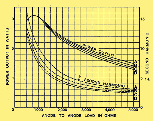
Fig. 3. The variation of power output with load impedance for a single valve is shown here. Curves A, B, C and D are for anode currents of 60, 65, 70, and 75 mA. respectively.
Referring to the curves of Fig. 3, which show the available power output, the anode load can be reduced to a value giving as much as 8% second harmonic with a corresponding increase in power output. For a single valve working at an anode voltage of 200 and a current of 70 mA, a load of 2,000 ohms is preferable, as variations between valves become more apparent at lower anode loads. With push-pull, an anode to anode load of 3,000 is recommended.
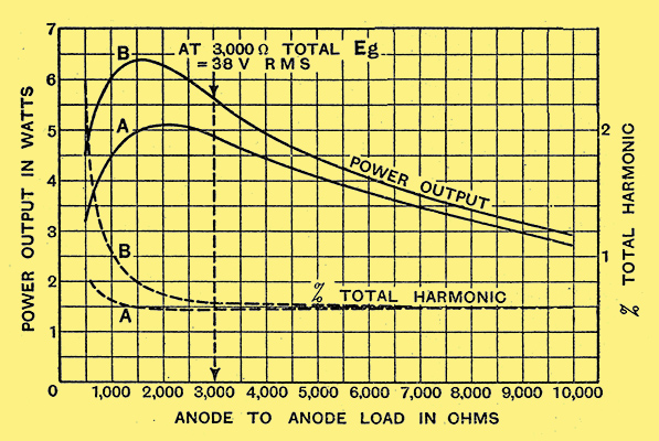
Fig. 4. The performance obtainable when two valves are used in push-pull is illustrated by these curves..
The curves of Fig. 4 show the output obtainable with push-pull operation with a quiescent teed current of 70 mA per valve, self-bias being employed.
Curve A represents the condition for an input equal to the quiescent bias (25 Volts peak per valve). Due to the curvature in the characteristic, the anode current will increase when an input swing is applied to the valve, thus increasing the working bias.
Curve B illustrates the power output when the input swing has been readjusted to a value sufficient to swing to zero grid volts. The input swing required to give Curve B will depend upon the anode to anode load, as the anode current rise will increase as the anode to anode load is decreased. For an anode to anode load of 3,000 Ohms the input swing had to be increased to 26.9 Volts peak per valve.
Twice the power output given in Fig. 3 will be the power output that will he obtained on transient inputs for push-pull working, while Curves A and B of Fig 4 illustrate the power output that can be obtained on inputs of constant magnitude.
The distortion curves plotted on this sheet represent the total audio harmonic present in the output, and this only represents the condition with two practically matched valves. The distortion actually present in a given push-pull stage will depend entirely upon the, degree of matching between individual valves, but in any combination the distortion present should be under five per cent when the valves are used under the recommended conditions.
It will be observed that a greater anode efficiency, i.e., ratio of power output to power input, can be obtained by using lower anode loads and feed currents.
Lower anode load should not be confused with the so-called low-loading conditions, for which the valve is not designed. The values of load and feed current recommended have, however been selected to take care of variations between valves, and to eliminate the necessity for accurate matching.
data-sheet .
|