|
After summarising the fundamental facts on the working principles of HF valves, with particular reference to the modern SG type, the author directs attention to the important practical requirements necessary to avoid the condition of flatness of tuning so commonly met with in screen-grid HF amplifiers. In addition, the recently introduced metal-sprayed valves are described and their advantages explained.
When the screen-grid valve first made its appearance it was hailed as the panacea of the radio ills which beset the ambitious set designer, with the regrettable result that a truly excellent invention has sometimes incurred criticism far beyond its deserts. In the short period during which the valve has been generally available a number of unsuspected phenomena have come to light demanding modifications of. conventional circuits. Unless the peculiar properties of the screened valve are understood the surrounding circuits cannot be designed to give the highest efficiency. In this article, development from the earliest HF valves to the latest metal-sprayed mains valves will be briefly discussed and typical circuits suggested for a compromise between the conflicting requirements of selectivity, amplification and stability.
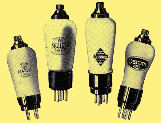
The new metal-sprayed valves. On the left is the Mazda battery 215SG valve next to the Mullard S4VB. On the right is the Cossor MSG/HA valve for AC mains and the Osram MS4. On the outside of the bulb is a thick metal coating connected to earth which acts as a valve screen.
In the early days of broadcasting attempts were made to amplify at high frequency, using the three-electrode valve, with the result that uncontrollable self-oscillation occurred before there was a perceptible increase in signal strength. In the light of more recent mathematical treatment of HF amplification it can be shown that an anode-to-grid capacity of 10 micro- microfarads (pF), the likely capacity of one of the earlier triodes, is sufficient to feed back energy enough within the valve to cause instability when the stage gain is about two. High-frequency amplification in these circumstances is impossible.
Then came the neutralised triode circuit in which the valve capacity was approximately balanced out by a bridge. Receivers containing this arrangement were extremely popular until Waveband switching became essential; then the complication involved was serious. A stage gain of about 40 on the medium waves was possible, but it must be conceded that complete stability across the tuning range was not always easy to obtain. The valve capacity is by no means a pure capacity and cannot theoretically be balanced out by at neutralising condenser except at one specific wavelength.
Just at the time when there appeared to be an impasse the 'shielded-plate' valve appeared, in which a screen, earthed to high-frequency currents, was interposed between grid and anode. This had the effect of reducing the inter-electrode capacity in the early samples to a value about 1/100th of that in the triode. To prevent the screen, which has to consist of a close-meshed structure, from restricting the flow of electrons, a positive potential is applied to it, so that there can be considered to exist, for the sake of argument, two anodes. The ideal curve connecting anode current and anode voltage for a four-electrode valve is shown as X Y Z in Fig. 1.
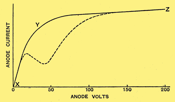
Fig. 1. - Characteristics showing the high impedance of a screen-grid valve.
Since the screen is of fine texture, the anode will only be able to take current from it and not be able to produce any extra current for itself.
High Impedance of the Screen-grid Valve
If now we gradually increase the anode voltage from zero the anode current will rise rapidly from X to Y, and as soon as the anode has robbed the screen of practically all its current a further increase in HT potential cannot help the anode to collect any more electrons, hence the curve becomes practically horizontal between Y and Z. Now, as the impedance of a valve is measured by the change of anode voltage divided by the change of anode current (and the current change is negligible along YZ), it will at once be appreciated why the screen-grid valve is necessarily of high impedance and fundamentally different from the triode. In practice the working curve is not quite the same shape as X Y Z. Should the screen voltage rise above that of the anode, the screen will rob the anode of secondary electrons which are always to be found around an electrode which is being bombarded. For a short distance the curve will show a decrease in anode current for a rise of applied potential, and the working characteristic is given by the dotted line (Fig. 1).
This so-called negative resistance kink in the curve must be avoided in a screen-grid amplifier by keeping the anode voltage at least twice the screen voltage, otherwise there is a danger of self-oscillation taking place. That the anode and screen currents when added together form a constant can be seen from Fig. 2. Where the anode current rises the screen current drops, and vice versa. The two curves have the same shape, but one being reversed causes a symmetrical pattern.
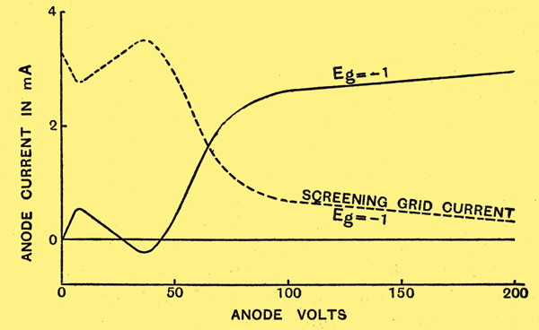
Fig. 2. - The sum of the currents of the screening grid and the anode at any point forms a constant. When the anode current decreases the screen current increases and vice versa.
The first commercial screen valves had inter-electrode capacities of 0.05 to 0.1 micro-microfarads (pF), this being sufficiently large to prevent any stage gain greater than that of a well-designed neutralised triode. It was pointed out in The Wireless World in July, I929, that a limit to stable amplification was to a large degree set by anode-grid capacity, and that if figures for this constant were published, calculations of HF amplification with various tuned circuits could be made. Subsequently a number of manufacturers measured the capacity, and by dint of research into the construction of screens we have to-day SG valves with two screens in cascade, cross-mesh and staggered screens, and other complicated constructions, giving residual capacities of the remarkably low figure of 0.003 and 0.002 μμF. It is important to realise that the better the mutual conductance the lower the residual capacity must be to maintain stable amplification.
Simple calculation shows that with the latest type of valve it is possible to obtain a stage gain of over 200 with quite modest components, provided that the external screening of coils and components generally is carried out with meticulous care. As to whether it is expedient to use such high amplification with a single stage especially if ganged circuits are employed, is another matter and involves many problems. In spite of certain limitations, most of which have come to light recently, the screen-grid valve has a great advantage over its predecessors. Considerably greater amplification is possible per stage, a number of stages in cascade (and ganged) are perfectly manageable, waveband switching is comparatively simple and reaction can be used without aerial re-radiation. This, indeed, is a formidable list of advantages.
Different Coils Require Different Screen Voltages
Consideration will now be given to the potentials which should be applied to the various electrodes. The control grid with the battery-type of valve need not be biased negatively by more than 0.9 Volt. A battery giving this voltage has been developed for The Wireless World by Messrs. Siemens Bros., and can be used with confidence. With mains valves, in order to prevent the signal from encroaching into the grid-current zone, at least 1.5 Volts negative bias is required. This can be obtained most conveniently by 'self-bias', using the voltage drop in a resistance in series with the anode-current return circuit. The anode voltage of a screened valve is not critical, but should be kept as near the makers maximum figure as possible. Screen voltage, on the other hand, is rather critical and, incidentally, controls the anode current far more than the anode potential. As the screen current is likely to be a milliamp. or less it is unsafe to feed this electrode through a series resistance from a point of high potential, for small changes in current would be accompanied by comparatively large changes in applied pressure. Use should be made of a potentiometer shunted across the anode supply so arranged in value to pass about four times the screen current.
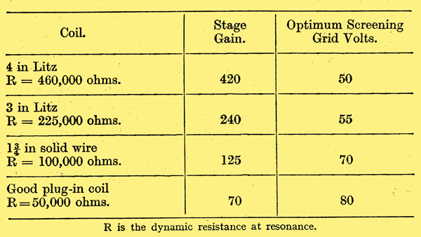
The impedance, amplification factor and, therefore, mutual conductance of a screen-grid valve are so profoundly modified by the screen voltage that it is impossible to quote these constants unless the exact conditions of measurement are specified. Since stage gain depends, in the case of tuned-grid and tuned-anode coupling, upon the relation between the internal and external impedance, also the working amplification factor, there will be only one screen voltage giving maximum amplification. It is quite possible for a good tuning coil to require only half the screen volts demanded by a bad coil. In Table 1 are given the optimum screen volts to obtain the highest possible stage gain with different coils. The figures are taken from The Wireless World. laboratory test of the Cossor 215SG valve. In the case of poor coils the valve has to supply more power to compensate for the losses in the tuned circuit.
Table 1
As a generalisation it can be said that the higher the impedance of a valve the more curved are its characteristics. Screened valves, therefore, with impedances of a megohm and half a megohm must perforce suffer from non-linear properties, and it was not until the advent of certain powerful stations, both in this country and abroad, that a number of aggravating interference effects were really brought home to the amateur using these valves. It is possible, as a result of the curvature referred to, for the signal voltage of an unwanted station to be rectified and for the low-frequency impulses to modulate the carrier of the wanted station so that the two stations are heard together, although the selectivity of the tuned circuits is ample to separate the two stations in the ordinary way. This is known as cross-modulation, and to preclude any but the desired station from being impressed upon the grid of the first valve it is almost essential, under modern conditions, to use a pre-selector or band-pass input circuit. Furthermore, to ensure that cross-modulation Will not occur at one end of the waveband, it is desirable to use an input filter with constant peak separation.
Another aid is a pre-HF volume control, which may take the form of a potentiometer in the aerial circuit and may be ganged to a second volume control arranged to adjust the screen-grid or control grid voltage of the first HF valve so as to reduce the level of valve noise. as the signal strength is de-creased. On no account should the volume of a loud signal be reduced by altering screen or bias volts unless the signal input is decreased at the same time.
The greater the load in the anode circuit, that is, the better the coil, the worse is the cross-modulation likely to be. This suggests that the anode should be tapped into the coil, which also has the effect of throwing the anode-screen capacity on to a portion only of the tuned circuit.
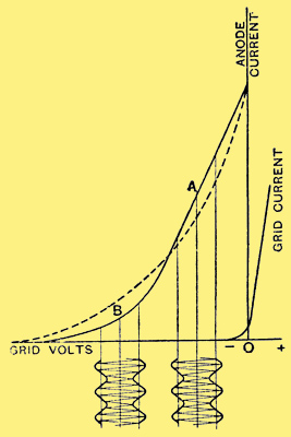
Fig. 3. - Showing how a curved characteristic can produce cross-modulation and modulation distortion.
In Fig. 3 an ideal screen-grid valve characteristic AB is shown. When the signal is applied at B cross-modulation would be very evident, but absent when working at A. The average characteristic of a modern valve is more like the dotted curve in which cross-modulation could occur at any bias point.
There is another effect due to partial rectification. The positive fringe of the modulated carrier may be amplified more than the negative fringe and the output of the valve will contain a greater average modulation than the original, resulting in distortion, A third effect, due to the same cause and especially evident when the valve is worked with a large bias, is the production of modulated hum in the case of mains valves. Happily these last two annoyances are reduced very considerably by applying the remedies for cross-modulation, and by maintaining optimum voltages on the electrodes of the valve.
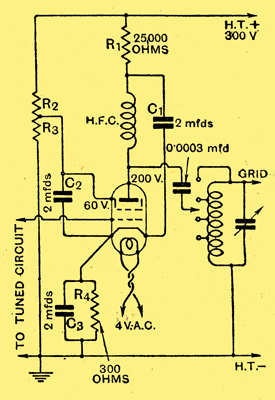
Fig. 4. - A typical screen-grid stage. Note that the anode is tapped into the grid coil to ensure stability, a minimum of cross-modulation and the transfer of only a fraction of the anode-screen capacity across the tuned circuit. The tuned input circuit should be of the band-pass type.
A typical screen-grid circuit for a single stage of amplification using a mains valve is given in Fig. 4. Assuming that the valve requires a negative bias of 1.5 Volts when the screen and anode have applied voltages respectively of 60 and 200, and that the screen and anode currents are 1 mA and 4 mA we can work out the values of the various voltage-dropping and de-coupling resistances, also the self-bias resistance R4. With power-grid detection and high-voltage pentode output, the anode potential for the HF stage is likely to be about 300 Volts. The anode de-coupling resistance R1, therefore, must drop 100 Volts at 4 mA. and must be made equal to 100/0.004 = 25,000 Ohms.
The value of R4 - the self-bias resistance - must be such that 5 mA. - the total anode and screen current - cause a voltage drop of 1.5 Volts. From Ohms law we get R4 = 1.5/0.005 = 300 Ohms. With modern SG valves this form of bias has no detrimental effect, since a considerable difference of potential between, cathode and heater can now be tolerated. The only grid de-coupling needed is the 2 μF. capacitor C3 across R4.
As it is difficult to prevent small leakage currents of about 0.5 to 1 microampere from flowing in the grid circuit of a mains valve it is not advisable to decouple this circuit with high resistances of the order of 1 megohm. One microamp of leakage current through 1 megohm will cause a positive bias of 1 Volt which will cancel the negative bias, and the resulting selectivity will be appalling.
The screen potentiometer R2, R3 must be of such a value that 60 Volts are applied to the screening grid, and that about 4 mA are wasted when the valve is cold. If R2 is made 50,000 Ohms, and R3 15,000 Ohms, these conditions will be satisfied. It is important that the screen-cathode capacitor C2 should be non-inductive and possess a small fraction of one ohm HF resistance at, say, 1,000 kHz. If any appreciable impedance is connected at this point the valve will behave like a triode and lose its attractive HF properties.
Valve hiss is much accentuated by a high external resistance between grid and cathode; it is, therefore, not desirable to use two stages of tuned anode coupling unless the grid leak of the second valve has a very low value.
To eliminate valve rectification in HF stages, to which considerable attention has been drawn lately, it would appear that development may lie in the production of a low-impedance screened valve, such as a screened pentode, as suggested in The Wireless World in December 17th, 1930, issue, or the 'variable-mu tetrode'.
Readers will be interested in the new metal-sprayed valves, illustrated herewith, in which a thick coating of zinc covers the bulb and is connected internally to the cathode in AC valves and to one of the filament pins (suitably marked) in battery valves. The earthed shield so formed avoids the necessity of using a separate cylindrical valve screen, and assists in minimising hum and stray coupling. By virtue of continuing externally the internal screen between anode and grid the coating also has the effect of reducing the working inter-electrode capacity. It must be remembered that should the metal covering touch any earthed screening boxes the bias resistance (if grid potential is derived as in Fig. 4) will be short-circuited, and in a battery valve if the wrong filament leg is earthed the LT battery might be damaged. It is understood that these valves will be sold at the same price as the ordinary valves. Metal-sprayed detector valves, with which screening is of particular importance, will also be available. Output valves will not be screened in this way.
|