|
A Locked Oscillator Discriminator
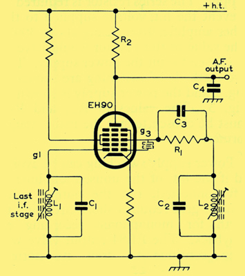
Circuit diagram of locked oscillator discriminator for FM sound transmissions with the 625-line television system.
When the 625-line television system is introduced in this country (UK), frequency-modulated sound transmissions will be used. This article describes a circuit which will be particularly suitable for use in the detector stage of the FM sound circuit.
Inter-carrier Technique of FM Sound Transmissions
In the proposed 625-line television transmissions, use will be made of FM sound which will be transmitted using the inter-carrier technique. In this system, the vision signal is amplitude-modulated and the sound signal frequency-modulated. Both signals can be amplified by the same chain of RF and IF stages and this results in economy in receiver design.
The FM sound IF carrier is produced by a heterodyne action between the sound and vision carriers with the vision detector acting as mixer. The resulting 6 MHz sound IF carrier is independent of local oscillator tuning which is then required for optimum picture adjustments only. Thus the FM sound is not subject to tuner drift and consequently, FM sound transmissions are very suitable for UHF broadcasting since, at these frequencies, receiver tuning is particularly difficult with AM sound signals.
The 6 MHz sound IF is amplified in a conventional manner and passed to the FM detector. An economical form of detector has been devised utilising the Mullard valve, type EH90. The two functions of demodulation and amplitude limiting are both performed by the EH90.
Locked Oscillator Discriminator
The circuit of the locked oscillator discriminator is shown above. The principle of operation is that the magnitude of the mean anode current in the EH90 is a function of the phase relationship between the voltages at the two control electrodes g1 and g3. The tuned circuits associated with these grids are described as being electron coupled. They may be regarded as being coupled by a negative capacitance. The negative sign indicates that energy is supplied by the electron stream in the valve, and this implies that amplification can be obtained between g1 and g3. As is normal with loosely-coupled circuits, the phase angle between the two voltages is 90° at resonance.
Circuit Description
In the diagram above, the last IF transformer L1C1 is physically separated but electrically coupled to tuned circuit L2C2. As in the Foster-Seeley phase discriminator, where at resonance the phase difference is 90° between primary and secondary voltages, the voltage across L2C2 at resonance is 90° out of phase or, to use another term, is in phase quadrature with the voltage across L1C1. Since L2 and C2 are in the circuit of the second control grid g3, this grid is known as the quadrature grid.
The inter-electrode capacitance Cg3-g1 of the EH90 provides feedback within the valve, in the manner of a tuned-anode/tuned-grid oscillator, and maintains oscillations. Capacitor C3 and resistor R1 are the normal grid leak and bias arrangement.
If the signal input changes in frequency, the oscillator remains frequency-locked but, as in the Foster-Seeley discriminator, the phase relationship between g1 and g3 changes in proportion to the change in signal frequency. The effective vectorial sum of the currents is shown as a voltage across load resistor R2.
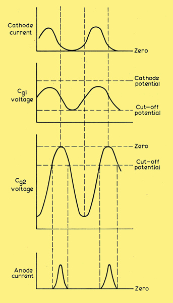
Voltage and current waveforms of discriminator.
In the absence of any deviation, the circuit conditions are as shown. Deviations in carrier frequency resulting from the modulation cause a corresponding change in the anode current. Anode load resistor R2 and capacitor C4 form a de-emphasis network and RF bypass.
If the signal input voltage is low, the magnitude of the voltage across L1C1 is determined largely by the oscillator condition. Therefore, the net effect of small amplitude variations of the input signal are effectively swamped. This action in no way affects the phase discriminator properties of the circuit. At high signal levels, the grid-cathode 'diode acts as a dynamic limiter. The high gain of the EH90 enables an un-bypassed cathode resistor to be used and the degeneration so provided further improves the AM suppression.
This type of circuit is not generally found in FM radio receivers because of difficulty in tuning-in the signal. This problem does not arise in the case of inter-carrier sound since the signal is pre- tuned and is unaffected by tuning the local oscillation of the set. Again, with an inter-carrier sound system, a separate automatic gain control circuit for FM sound is not required since this is provided for by the normal vision AGC which is applied to the common vision and FM sound IF stages. Thus for the proposed FM sound transmissions with the 625-line television system, the EH90 locked oscillator discriminator offers advantages in terms of performance and simplicity of circuit design.
|