|
In the past all stereophonic amplifiers have been fairly large for the reason that even the smaller designs required two output valves (one for each channel), whilst the larger push-pull stereo amplifiers required a total of four output valves.
In order to reduce the number of separate valves required in such equipment and to keep costs to a minimum, a small double pentode known as the ELL80 having a Noval (B9A) base has been introduced. The ELL80 is available from Brimar Ltd. A single valve of this type can be employed as the output stages of both stereo channels in an amplifier providing a power output of some 3 Watts per channel. It is therefore especially suitable for use in economical stereo amplifiers which must be small and reasonably portable for domestic use. An ELL80 may also be used to provide a class AB1 push-pull output stage for monaural amplifiers, whereupon a power output of 8.5 Watts is available.
Three Valve Stereo Amplifier
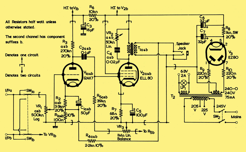
Circuit diagram (one channel). Mains transformer: G B Electric type GB2553. Output transformer G B Electric type GB2551. This circuit was originally published by Brimar under the name of 'Brimar Three Valve Stereo Amplifier'.
The circuit of one channel of a compact stereo amplifier using only two valves plus rectifier for AC mains operation accompanies this article. The circuit of the other channel is identical. The components marked a and b must be duplicated for the two channels, but the other components (e.g. the cathode bias resistor and condenser in the ELL80 circuit) need not be duplicated, they being common to both channels. The power supply circuit is also common to both channels.
The input voltages are amplified by the 12AX7 high gain double triode. One half of this valve is used in each stereo channel. The signals then pass via the RC couplings to the ELL80 double pentode; one half of this valve is also in each channel. Negative feedback is used in both channels. It is taken from the output transformer secondaries and is applied to the cathode circuits of the 12AX7 by means of the potential dividers R4 a and b, and R1 a and b. The rectifier is an EZ80.
Controls
The ganged volume control, VR1 a and b, alters the gain of both channels simultaneously. The ganged potentiometer, VR2 a and b. can be used to provide a top cut of up to 18dB at 10 kHz simultaneously in both channels. The balance control, VR3, enables the relative gain of the two channels to be altered by about 5dB.
The amplifier can also be used to provide approximately three Watts of audio output from a monaural input. By means of the switch SW1a and SW1b), both channels can be operated in parallel (monaurally) from either input socket.
Performance
The amplifier gives its maximum power output of 1.5 Watts per channel at 3.5% total harmonic distortion with an input of 150mV RMS.; it is thus suitable for use with a high output pick-up head. The frequency response is level to within 3dB from 50 Hz to well above the highest audio frequencies. The hum and noise is 55dB below the full output and 'cross-talk' between channels is very small. The amount of negative feedback is 6dB.
The 6DY7 Valve
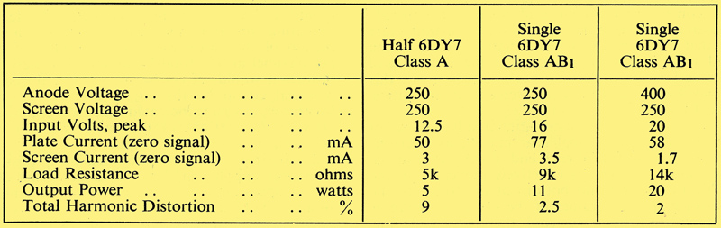
Typical Operating Conditions for Type 6DY7. A data-sheet can be found here.
ln America, the Sylvania Company has evolved a high performance double tetrode known as the 6DY7. A single 6DY7 used as the output stages of a stereo amplifier will supply up to 5 Watts of audio per channel. The 6DY7 has an octal base. Whilst this valve has been especially designed for use in stereo equipment, a single valve of this type is also very useful in push-pull monaural amplifiers, giving a low distortion and a high power output.
Frame Grids
The wires of both the control and screen grids of the 6DY7 are mounted on rigid rectangular frames under slight tension. This type of construction enables the dimensions (especially the cathode-grid spacing) to be controlled much more accurately than in conventional valves in which the grid wires help to keep the grid side wires in position. This results in closer tolerances in the characteristics from valve to valve and renders changes of the characteristics small during the life of a valve even at high power dissipations. Such close tolerances are important in this type of valve because it is obviously not possible to select well matched pairs of valves for a push-pull stage when the two valves are enclosed in one envelope.
In the 6DY7 the grid wires are exactly perpendicular to the sides of the frame. The diameters of the control and screen grid wires are carefully chosen and the grids are aligned during manufacture so that virtually the whole length of each screen grid wire is 'in the shadow' of the control grid wire as far as the electron beam is concerned; this achieves excellent anode to screen current ratios.
The control grid of conventional valves does not always exert full control near cut-off, as electrons tend to slip through at each end of the grid near the mica supports. This is effectively prevented in the 6DY7 by the top and bottom of the frame of the control grid. The frames of the grids also serve as heat sinks, helping to cool the grids and thus preventing any change of characteristics due to expansion of the grid wires.
A single cathode is employed and the two screen grids have a common base connection in order to limit the number of external connections to eight in order that an octal base can be used. In fact the construction of the valve is similar to a single beam tetrode in which the two sides of the control grid are electrically insulated from each other, as are the two sides of the anode.
The type of grid used is known as a 'Framelok' grid and is very different from the frame grid described previously by the author in The Radio Constructor.
Practical Uses
The following examples illustrate the versatility of the 6DY7 in practical circuits.
- A single 6DY7 can be used as a power amplifier for two stereo channels. Under the operating conditions shown in the table for a single section of the valve, the power output is 5 Watts per channel at 9% total harmonic distortion. The distortion would, of course, be vastly reduced in a practical circuit by the use of negative feedback. Measurements have indicated that cross modulation between the sections of the valve is about 50dB below signal level at full output.
- A single valve can, be used as a push-pull monaural amplifier in class AB1 under either of the sets of operating conditions shown in the table. If an anode voltage of 400 is employed, outputs of up to 20 Watts of audio at a total harmonic distortion of 2% may be obtained.
- Two 6DY7s may be employed in a stereo amplifier with push-pull outputs. Audio outputs of up to 20 Watts per channel can be obtained with this arrangement.
- Two 6DY7s may be used in a parallel push-pull monaural amplifier providing up to 40 Watts of audio output at about 2% distortion.
Conclusion
The use of the ELL80 and the 6DY7 will reduce the size of amplifiers, especially stereo amplifiers, and reduce the number of components, cost of wiring, etc.
Further details of the 6DY7, including circuits, are given in Transactions IRE on Audio, Vol. AU7 (1959), No. 4, page 101.
|