|
The circuit of the amplifier
The audio output in Watts which is needed to reproduce music realistically in a normal living room is a subject for argument. Many people will maintain that a minimum of 10-12 Watts is necessary with ordinary moving coil loud-speakers, and the writer is inclined to agree with this view: but nevertheless the results which can be obtained with an output of only 4 Watts are frequently surprisingly good, provided that this 4 Watts is delivered with very low distortion. The present amplifier design is suggested as fulfilling this requirement and is also both sensitive and economical. A pair of these small amplifiers for stereo use employing a common power supply, can be built for a price not much greater than that needed for a conventional 10 Watt monophonic push-pull amplifier.
The Output Transformer
The one component on which the quality of the amplifier depends is, as usual, the output transformer, and it is advisable not to try to economise on this. A nominal rating of 10 Watts is suggested: the prototype amplifier used a 20 Watt C core push-pull triode transformer (still quite small), and the excellent performance is no doubt related to this. There must, however, be many readers who have good quality output transformers rated at 10 Watts or more, designed for push-pull triode operation but without the tappings necessary for ultra-linear circuits. Such transformers are excellent for the amplifier here described, as the centre tapping on the primary winding approximates closely to the 43% tap preferred for the ultra-linear operation of a single-ended output stage.
The writer has used the prototype amplifier in direct comparison with a Mullard 20 Watt ultra-linear design using push-pull KT66 valves and giving a distortion of 0.05% and a damping factor of 50. The tests were conducted in a room roughly 18 x 12 x 10 ft (i.e. not by any means the smallest of modern-living rooms), and at full realistic listening volume the small amplifier was almost indistinguishable from the larger when both were operating a large three-speaker system. On exceptionally heavy passages, of organ music, the deep bass occasionally lacked the clarity-provided by the 20 Watt amplifier, but this only at a volume level which even an organist described as 'excessive'!
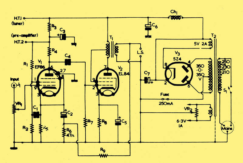
A perusal of the circuit diagram shows it to be fairly conventional. A low noise, pentode EF86 V1 is RC coupled to the output stage EL84 V2, the screen grid of the latter being fed from the centre-tap (ideally at 43% from the anode) to provide ultra-linear operation. Negative feedback is applied from the secondary of the output transformer to the cathode of V1, and the cathodes of both valves are bypassed to keep the overall gain as high as possible. The power supply uses a full-wave rectifier, and a smoothing choke is employed to keep hum to a minimum without needing large values of capacitances, though no doubt RC smoothing would also prove satisfactory. Provision is made for supplying power to both a preamplifier and an FM tuner, though if this is not required the size of the mains transformer can be correspondingly reduced. With the values given in the components list sensitivity is approximately 200mV for 4 Watts output.
Layout
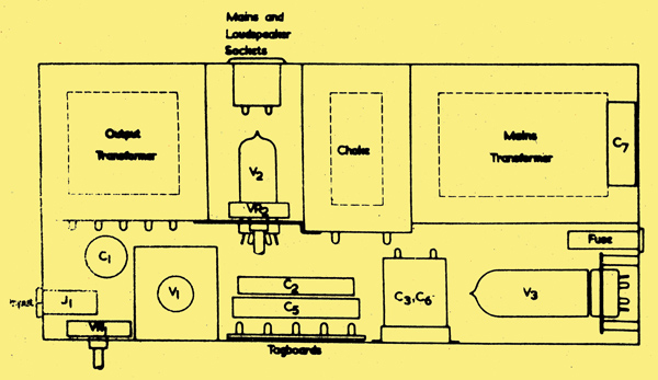
Diagram showing layout and position of the larger components. (See also text.) V1 is mounted vertically on a small aluminium bracket, which also supports C1. V2 is mounted below VR2 on an aluminium bracket held between the output transformer and the choke. C4 is not shown, being below C2 and C5.
The layout of the prototype amplifier is somewhat unusual but has proved very satisfactory, being surprisingly compact and well protected. A conventional metal chassis is not used instead, a rectangular wooden shell, open top and bottom, is used as the main framework. On the rear wall are placed the three heavy components - mains transformer, smoothing choke, and output transformer, with a small gap between the latter two for the mains input and loudspeaker sockets. Also in this space are mounted horizontally the output valve and the 'humdinger' potentiometer, VR1. The valve-holder and potentiometer are fixed to a small metal sub-chassis, which is in turn secured to the 'top' of the choke and output transformer.
The rectifier valve is also mounted horizontally, with the valve-holder fixed to the shell with wood screws but spaced from it by means of spacers. There can be sufficient room to employ a large rectifier of the international octal class as is used in the prototype. A miniature of the EZ80 type could alternatively be used. It is advisable to solder the leads to the valve-holder before mounting it in position. Above the valve-holder is the reservoir capacitor C7 (unless mounted as/ shown above). The EF86 (V1) is mounted vertically, its base being fixed to a small metal sub-chassis screwed to the wooden shell adjacent to the input jack and potentiometer VR1. The position of the remaining small components will be clear from the foregoing: small tag-boards or strips are easily screwed to the wooden shell to support them as necessary.
A further unexpected virtue of this method of construction results from there being no definite metal chassis, and hence no opportunity to make indiscriminate earth connections to it! Instead, an earth bus-bar is run round the amplifier, starting at the input jack and extending finally to the mains input socket earth connection, and all other earth connections are made to this. To keep hum down to a minimum, only one earth connection is made to ancillary equipment (pre-amplifier, tuner, etc.) and this will normally be via the shielding of the coaxial input cable.
One word of repetition. To realise the full potentiality of this small amplifier, it is essential to use an output transformer of the highest quality, preferably rated at a minimum of 10 Watts. After all, the design is still considerably simpler and cheaper than a genuine 10 Watt amplifier! And it provides an admirable use Tor any available push-pull triode transformer without the ultra-linear tappings.
Stereo Version
The design of a stereo version calls for no special comment: the circuitry of V1 and V2 will be duplicated, and the ratings of the power supply components increased accordingly. It is important that the output transformers are similar, and also that critical components such as anode load and bias resistors are closely matched. It is suggested that the input potentiometers be made concentric, but with separate operating spindles: in this way, an additional balance control becomes unnecessary. Other refinements such as channel reverse and speaker phasing switches can be added if required. though it seems to the author that these things should be settled once and for all at the time of initial setting up, and then left alone!
In conclusion, do not be misled by the simplicity of the circuit. If you still think that 10 Watts of undistorted sound are essential for real 'hi-fi' reproduction, build this amplifier and see. for yourself. You may be surprised!
Editor's Note
It should be pointed out that a single-ended output transformer normally has butt-jointed laminations (e.g. all the Es on one side and all the Is on the other) with spacing at the joint to prevent the formation of a complete magnetic circuit. The iron is thus less driven towards saturation by the constant DC in the primary. Push-pull transformers, on the other hand, normally have interleaved laminations (e.g. alternate Es and Is down the stack) because the steady DC currents in the primary cancel each other out. This fact also necessitates the use of a relatively large push-pull transformer in the single-ended circuit discussed here.
The output transformer ratio is experimental, but we would suggest a reflected anode load of some 4 to 5kΩ. The value of R9 may, also; require adjustment according to speaker impedance.
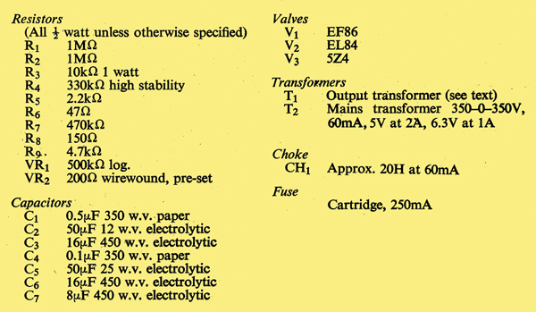
Components List
|