|
Its use as a Limiter and Discriminator for Frequency Modulation Reception
Advances in the art of frequency modulation reception seem all too often to come about only as a result of advances in allied, higher-powered fields. Exceptions to this rule do exist - for example, the MIT work on multi-path transmission [1] Arguimbau, L B, and Stuart, R, Frequency Modulation, Methuen and Co. Ltd., 1956. [2] Johnson, L W, FM Receiver Design, Wireless World, October 1956, p. 497. but it is safe to say that if it were not for radar and television, the low-noise front ends and compact IF amplifiers used in modern FM receivers would not be available. It is the purpose of this paper to describe the 6BN6 gated-beam tube, a television development which bears out the original contention. To the designer of FM tuners and receivers it brings a very useful tool in improving performance or in lowering price, whichever objective may be the more important.
The 6BN6 was developed in the laboratories of the Zenith Radio Corporation, by a group led by Dr. Robert Adler, and was first put into production by the General Electric Company (US). The basic ideas were not new, but Adlers work seems to have been the first to combine them all successfully. The prime purpose of the development appears to have been the simplification of the sound channel of television receivers. When the 6BN6 is so used it takes the place of the limiter, discriminator, and first audio stages, and at the same time eliminates the rather complicated phase discriminator or ratio detector transformer, substituting in its place a simple inductor resonant at the intermediate frequency [3] Adler, R, and Haase, A P, The 6BN6 Gated-Beam Tube, Proc. National Electronics Conference, Chicago, September 1949. [4] General Electric (US) Engineering Bulletin ET-B28, The Gated-Beam Tube and its Application in Inter-carrier Television.. The resulting FM detector does not meet the requirements set forth for an exceptionally high capture ratio [2] Johnson, L W, FM Receiver Design, Wireless World, October 1956, p. 497., but its performance equals or surpasses that of the commonly encountered ratio detector or single-limiter/discriminator. In some high-quality FM tuners the 6BN6 is employed as a broad-band limiter only, and is followed by a separate broad-band detector to assure a good capture ratio.
Counter Discriminators
Understanding the operation of the 6BN6 is not difficult if one falls back upon previously explained phenomena and circuits. Roddam [5] Roddam, Thomas, Why Align Discriminators? Wireless World, July 1948. and Scroggie [6] Scroggie, M G, Low-Distortion FM Discriminator, Wireless World, April 1956. have done much to familiarize readers of this journal with low-frequency versions of the counter type of discriminator, which presents several intriguing advantages, but also imposes limitations on bandwidth because of the necessarily low intermediate frequency. The 6BN6 may be thought of as a way of utilizing the same general principle as that of the counter discriminator, at an almost arbitrarily high intermediate frequency. This last-mentioned property might seem to provide a large advantage over other counter-discriminator systems in that an excellent capture ratio would seem to be within reach. That this is not completely true will be discussed in detail later envelope for envelope, however, the 6BN6 still provides several points of superiority over practical counter detectors.
The conventional counter detector utilizes the principles of pulse position modulation (PPM); it is supposed, ideally, to put out one pulse for each cycle of the incoming frequency-modulated voltage. It is assumed that the output pulse will have a standard height, duration, and shape, regardless of the input frequency and amplitude. The resulting train of pulses, identical in all respects save spacing, can be passed through a low-pass filter, at the output of which will appear the desired audio signal representing the demodulated wave. Fig. 1 shows an FM wave and an idealized counter detectors action. It is only a simple step to consider instead a system where the duty cycle (ratio of pulse duration to the full repetition period) instead of pulse spacing is varied. This is the scheme which the 6BN6 detector employs. Current pulses are formed which have standard height, rise time, and fall time; they vary in both width and spacing, but the significant fact is that the duty cycle, nominally 25% with no modulation, is made to vary in accordance with the deviation of the instantaneous input frequency from the fixed intermediate frequency. As before, the current pulses are passed into a low-pass filter, which yields an output proportional to duty cycle, thus conveying the desired modulation intelligence.
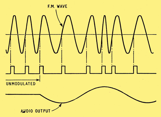
Fig. 1. Principle of the pulse counter detector.
Dual Control Grids
The details of the manner in which the 6BN6 accomplishes these functions are fairly straight-forward. For the present let it suffice to say that the 6BN6 has two control grids, well-shielded from each other, both of which are capable of cutting off anode current, and whose dynamic ranges are both quite small. Thus an alternating voltage on either electrode of a few volts amplitude, peak-to-peak, will cause pulses of anode current to flow as the electrode voltage is carried from cut-off to saturation and back. For reasons that will be clear later, the closer of the two grids to the cathode is called the limiter grid, and the other is called the quadrature grid.
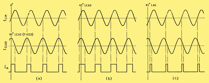
Fig. 2. Variation in pulse duty cycle for changes of phase between the limiter and quadrature grids. Anode current is assumed to flow only when both grids are positive.
Suppose now that an unmodulated signal is applied to the limiter grid, and that the same signal, advanced in phase by 90 degrees, is applied to the quadrature grid. (The reason for the name may now be growing apparent.) If the amplitudes of the two voltages are sufficient, either by itself would suffice to form pulses of anode current, and if one or the other were of zero amplitude, the other would cause the anode current duty cycle to be 50%. Fig. 2(a) shows how, with the application of voltages 90 degrees apart, the anode current duty cycle would be reduced to 25%. For simplicity, current is assumed to reach the anode only during the portion of the signal cycle when both grids are positive.
What happens if the phase of the voltage applied to the limiter grid is varied, while that of the voltage applied to the quadrature grid is kept steady as in the initial example? If the phase of the limiter grid voltage is advanced by 45 degrees, the anode current pulses will be as shown in Fig. 2(b); the duty cycle has been increased to 37.5%. Alternatively, if the phase of the limiter grid voltage is retarded by 45 degrees, the anode current pulses will be as shown in Fig. 2(c); now the duty cycle has been decreased to 12.5%. Bear in mind that Fig. 2 is for a voltage of constant frequency and unchanging phase applied to the quadrature grid, with variation only of the phase of the voltage applied to the limiter grid; these conditions are exactly what might be encountered in a phase detector. That is, such a circuit would provide a DC output that would vary in proportion to the phase difference between a variable-phase carrier-frequency input and a fixed-phase carrier-frequency reference input. The line between phase and frequency is a hazy one; if, for example, one speaks of a continuously changing phase, one may equally well speak of a frequency shift. Thus it is that phase detectors and frequency modulation detectors often have very similar circuits.
The 6BN6 phase detector can be used almost without change as a frequency modulation detector; it is necessary only to arrange somehow to supply an appropriate reference voltage to the quadrature grid. The signal to be detected will be applied to the limiter grid; a convenient result of the narrow dynamic range of the limiter grid is that amplitude modulation of the input signal will have little effect on the timing of the anode current switching.
Practical Circuit
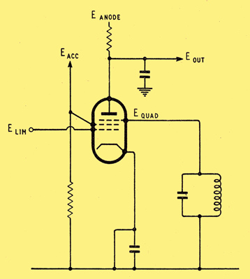
Fig. 3. Basic circuit of gated-beam limiter discriminator.
Fig. 3 shows the circuit actually used in the 6BN6 FM detector. The representation is drawn in the fashion of a pentode; more physical detail will be given later. The limiter grid is that nearest the cathode, while an accelerator or screen grid is between the limiter and quadrature grids. The signal to be detected is connected to the limiter grid, a moderately-high-Q resonant circuit is connected to the quadrature grid, a typical screen grid voltage is applied to the accelerator, and to the anode are attached a load resistor, an integrating capacitor (to earth), and a coupling capacitor (to the audio amplifier). With this circuit configuration, consider the situation when a signal is applied of the same frequency (the intermediate frequency of the receiver) as that to which the coil in the quadrature grid circuit is tuned. Under these conditions there is space charge coupling to the quadrature grid circuit as a result of the pulses of current passed by the limiter grid. There results a current in the quadrature grid circuit Whose frequency is that of the current pulses, and whose amplitude is broadly frequency-dependent. Thus there is produced a voltage from quadrature grid to earth at the input frequency, of amplitude sufficient to carry the quadrature grid considerably past the cut-off and saturation limits, so that the pulses of beam current produced by the limiter grid will be further modified before they become pulses of anode current. Just how they are modified is determined by the phase difference between the limiter and quadrature grid voltages. The quadrature grid circuit situation is analogous to that of a parallel resonant circuit fed through a small capacitive reactance; at resonance the voltage across the resonant circuit leads the current by 90 degrees, and at frequencies near resonance the lead angle is given by an approximation quite accurate for frequency deviations of 75 kHz or less, and for quadrature inductor Qs of 35 or less. The approximation states that
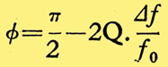
where θ is the lead angle in radians, Q is the figure of merit of the quadrature coil, ƒ0 is the intermediate frequency to which the quadrature coil is tuned and Δƒ is the deviation of the input frequency from ƒ0.
Linearity
From this relation it is clear that the anode current duty cycle is 25% when the input frequency is equal to the intermediate frequency. And further, as the input frequency is varied, it is clear that the phase difference varies in a linear fashion, producing a linear variation in duty cycle of the anode current pulses, along the lines of what was described earlier for the 6BN6 phase detector; for a frequency above the intermediate frequency, the duty cycle is less than 25%, and for a frequency below the intermediate frequency, the duty cycle is greater than 25%. This fortunate situation has resulted from quadrature circuit phase changes resulting from forced oscillations excited therein by means of space charge coupling from the beam current.
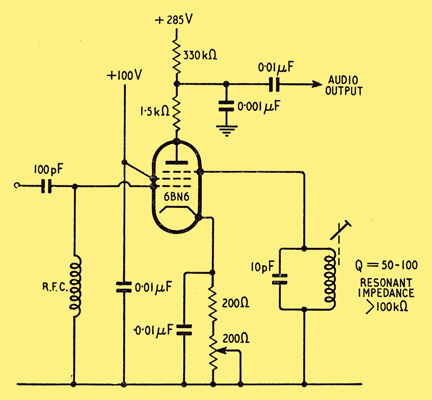
Fig. 4. Practical circuit with component values for the 6BN6 valve.
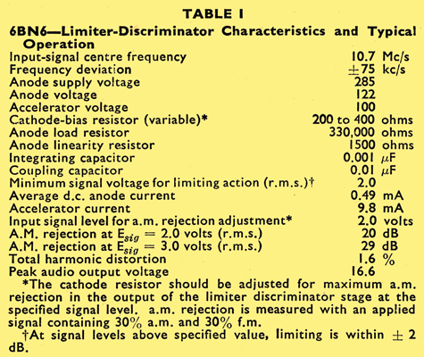
As before, the desired audio signal can be recovered by means of an integrator or low-pass filter. Appropriate choice of low-pass filter components can provide simultaneous de-emphasis, yielding further simplification of the circuit. The values shown in the detailed circuit of Fig. 4 are designed to compensate for the 75-microsecond pre-emphasis, standard in the US Also shown in Fig. 4 is an additional linearity resistor between anode and integrating capacitor. This resistor, by permitting an appreciable component at carrier frequency to exist at the anode, modifies the phase and amplitude of the quadrature grid voltage by feedback through the quadrature-grid-to-anode capacitance in such a fashion as to improve linearity considerably. This resistor also has some effect on the amplitude of the output voltage, and on the AM rejection capabilities of the circuit, so that its value represents a compromise between conflicting requirements. Table 1 gives the characteristics and typical operation furnished in the manufacturers technical data manual [7] General Electric (US) Receiving Tube Manual., from which the circuit of Fig. 4 was taken.
Simple Adjustment
Alignment of the circuit turns out to be admirably simple. The quadrature coil is tuned for maximum audio output, and the cathode resistance is adjusted for optimum AM rejection. Both these adjustments can be made without a signal generator; in fact the latter is very easily made when receiving a weak station in the presence of impulsive noise interference. It is important to note that symmetry of the tuning characteristic will be adversely affected unless anode current without signal equals anode current with an unmodulated signal. Thus the use of other supply voltages than those listed will require that the value of anode resistor be adjusted. It is desirable in addition that the accelerator be fed from a low impedance source.
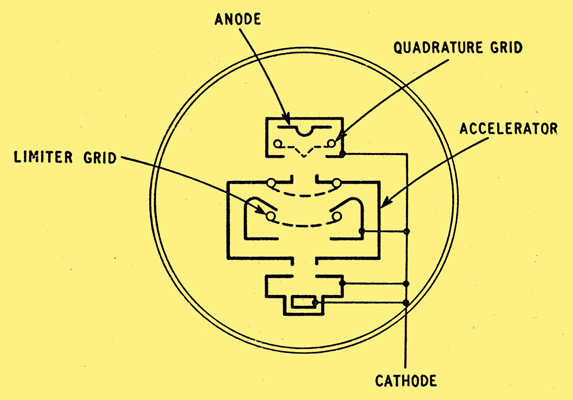
Fig. 5. Cross-section of electrode structure in the 6BN6 valve.
A cross section of the 6BN6 electrode structure is shown in Fig. 5. Note that the limiter grid is almost completely enclosed by a structure at cathode potential, which in turn is almost completely surrounded by the accelerator. Note also that the anode and quadrature grid are almost completely enclosed in another structure at cathode potential. With such a structure it should not be surprising that the direct capacitance between quadrature grid and limiter grid is less than 0.004 pF. The limiting action of both grids is accomplished by means of carefully planned electron-optical conditions. Either grid will draw no more than 0.5 mA no matter how far positive it may be driven, and the box structure, combined with the sheet-beam resulting from careful electrode layout, yields a sharp cut-off characteristic. In fact, as long as the signal applied to the limiter grid is above about two volts RMS, the space current which passes out of the accelerator is carried rapidly from zero to the saturation value; consequently the name limiter grid is justified, for any larger amplitude of input voltage will only sharpen the transition from zero to the saturation value.
The Q of the quadrature coil can vary between fairly broad limits. On the one hand, it must not be too sharply tuned, or the amplitude of the quadrature voltage may drop off at large deviations, and the phase deviation may depart from linearity. On the other hand, it should not be too broad, since there is then danger of insufficient quadrature grid voltage as a result of the reduced quadrature coil voltage. As a practical matter to insure continuity of operation with valve replacement, the manufacturer recommends that a total of at least 10 pF of capacitance be used across the quadrature coil. Needless to say, careful shielding of the quadrature circuit is necessary, especially from the input circuit to the limiter grid. Broadening the quadrature coil tuning will aid in broadening the bandwidth of the 6BN6 detector, but it appears that the practical upper limit will still not permit its use in a design which calls for a two- or three-megaHertz detector bandwidth. Nevertheless the circuit fits well the requirements of low cost receivers, since it will still provide a greater-than-normal bandwidth while providing a high output voltage, thus contributing to the simplicity and low cost of such a receiver while keeping quality reasonably high.
Use as a Limiter
The characteristics of the limiter grid suggest that the 6BN6 can be profitably employed as a pure limiter. This is in fact the case. For use as a limiter the manufacturer suggests that the quadrature grid should be connected to the anode if the maximum amplitude of output voltage is desired, or to earth if limiting on the smallest possible input signal is desired. Particularly desirable in a limiter is the characteristic of the 6BN6 that results from its electron-optical design; limiting does not depend on flow of grid current, nor in any way on biases determined by signal levels. Thus there are no time constants associated with the limiting action, which cannot be said to be true of the familiar pentode limiter, or even of some diode limiters. Thus the 6BN6 provides improved immunity from impulse interference and from rapidly changing signal levels, in contrast to the pile-up effect characteristic of pentode limiters. These several advantages have led to the appearance of the 6BN6 as a limiter in several high-quality FM receivers. It may be that its failure to appear as a limiter-discriminator in inexpensive tuners is attributable to a stigma based on its television cost-cutting background. Such a reluctance is certainly not justified, since the 6BN6 when properly used can out-perform the presently popular ratio detectors and discriminators used in inexpensive equipment.
A detailed study of the gated-beam limiter at MIT [8] Price, R A, A Study of the Gated-Beam Limiter, MS Thesis, Department of Electrical Engineering, MIT, Cambridge, Mass., 1953. bears out the conclusions stated above about the excellence of its properties. The study recommends separate control of the biases on limiter and quadrature grids for optimum adjustment of limiting characteristics. This appears to be desirable because of variations in characteristics from valve to valve. Cascaded 6BN6 limiters with earthed quadrature grids were used in the Cross-Paananen receiver developed at MIT [9] Cross, H H, Head End Design for FM Tuner, TV and Radio Engineering, February-March, 1953. [10] Paananen, Roy, IF and Detector Design for FM, TV and Radio Engineering, April-May, June-July, and August-September, 1953., and mentioned in an earlier article in this journal [2] Johnson, L W, FM Receiver Design, Wireless World, October 1956, p. 497..
A recently announced RCA development [11] Avins, J, and Brady, T J, A Locked-Oscillator Quadrature-Grid FM Sound Detector, RCA Review, December 1955, p. 648. seems to be very similar to the 6BN6 detector circuit described above. The circuitry is essentially identical, but the operation differs in that the detector is normally oscillating, and only for strong signals does the oscillation cease. For weak signals the action is along the lines of the locked-oscillator detector, developed and used some years ago [12] Bradley, W E, A New Detector for Frequency Modulation, Proc. National Electronics Conference, Chicago, October 1946.. There is no indication that the 6DT6, the special pentode developed for this circuit, possesses the electron-optical limiting characteristics of the 6BN6. It is possible that a marriage of the two schemes, combining the good features of both, would prove interesting. Presumably such an approach would involve modifying the 6BN6 circuit so that it would oscillate for low values of input signal.
DC Component
There is a characteristic of the 6BN6 detector that may be considered by some to be a disadvantage. There is present at the anode a DC voltage which varies in the fashion required for control of an automatic frequency control circuit, except for the fact that the voltage level for centred tuning is not zero but is instead of the order of 100 Volts. This makes difficult, but not impossible, the job of designing an AFC circuit, the need for which might better be counteracted by devoting care to the design of the local oscillator.
Tuning meters can easily be used with the 6BN6 circuit; the limiter grid current, never greater than one half milliampere, is a wonderfully sensitive aid in tuning weak stations, while for strong stations the grid current of the preceding intermediate frequency amplifier stage - which would be the logical source of automatic gain control voltage in a 6BN6 receiver - provides a sensitive indicator. The provision of a zero-centre on-channel indication falls in the same category as providing AFC, however.
Modification of existing equipment to employ the 6BN6 as a limiter-detector is quite practical, and in most cases will yield an improvement.
Existing limiters can be converted to additional intermediate frequency amplifier stages by appropriate adjustments of their operating conditions, and the discriminator or ratio detector transformer can often be converted into a driver transformer for the 6BN6 limiter grid. Room for a shielded quadrature coil must be located. The DC resistance in the 6BN6 limiter grid circuit should be kept under 200Ω, lest the flow of grid current upset bias conditions. The results of such a modification will generally be as follows:- sensitivity will be increased, noise rejection will be improved, alignment will be easier, and tuning will be easier. This last feature is perhaps as welcome as any of the others. It results from the fact that the broader-than-usual bandwidth of the 6BN6 detector effectively eliminates the three-point detection usually encountered, substituting instead a broad region of smooth tuning with noisy regions on each side which result from slope detection in the intermediate frequency amplifier and consequently present a highly amplitude-modulated signal to the limiter grid. This tuning characteristic makes it convenient to design an inter-station squelch circuit activated by the super-audible components present in the inter-station noise.
In closing it might be noted that many applications other than those mentioned have been found for the 6BN6. It is useful as a clipper, square-Wave generator, frequency multiplier, gated amplifier, coincidence circuit, slicer, or multivibrator. And finally, it seems to be the only tube which can be self-biased to anode-current cut-off.
References
- Arguimbau, L B, and Stuart, R, Frequency Modulation, Methuen and Co. Ltd., 1956.
- Johnson, L W, FM Receiver Design, Wireless World, October 1956, p. 497.
- Adler, R, and Haase, A P, The 6BN6 Gated-Beam Tube, Proc. National Electronics Conference, Chicago, September 1949.
- General Electric (US) Engineering Bulletin ET-B28, The Gated-Beam Tube and its Application in Inter-carrier Television.
- Roddam, Thomas, Why Align Discriminators? Wireless World, July 1948.
- Scroggie, M G, Low-Distortion FM Discriminator, Wireless World, April 1956.
- General Electric (US) Receiving Tube Manual.
- Price, R A, A Study of the Gated-Beam Limiter, MS Thesis, Department of Electrical Engineering, MIT, Cambridge, Mass., 1953.
- Cross, H H, Head End Design for FM Tuner, TV and Radio Engineering, February-March, 1953.
- Paananen, Roy, IF and Detector Design for FM, TV and Radio Engineering, April-May, June-July, and August-September, 1953.
- Avins, J, and Brady, T J, A Locked-Oscillator Quadrature-Grid FM Sound Detector, RCA Review, December 1955, p. 648.
- Bradley, W E, A New Detector for Frequency Modulation, Proc. National Electronics Conference, Chicago, October 1946.
|