|
My object is to explain as simply as possible the elementary principles of the valve. For the purpose of this little talk I intend to make a very free and easy translation of the words 'elementary principles', because I believe that what you wish to know to-night is what the valve is, how it works, and why it works. I do not intend to deal with the evolution of the valve, but to come at once to the modern three-electrode valve in almost universal use in wireless receiving sets.
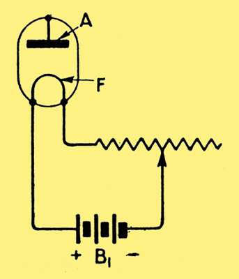
Figure 1.
In Fig. 1 is shown a loop (F), the extremities of which are shown connected to the positive and negative terminals of a four-volt battery shown conventionally at B1. If the wire of which the loop F is made has an appreciable resistance, the passage of the current from the battery will raise the temperature and the wire may become red hot or even incandescent.
In order to control the current flow through the loop, and consequently the heat of the loop, an additional and variable resistance, or rheostat, is introduced between one side of the battery and the loop of wire. When the temperature of the wire is raised sufficiently, minute negative charges of electricity, called electrons, commence to be emitted from the wire. The electrons, normally in a kind of regular planetary movement within the atoms of the wire, are violently agitated by the increased temperature, and are emitted from the surface of the wire.
In order to obtain a plentiful supply of electrons the wire loop must usually be raised to incandescence, but if this was done in air, the wire forming the loop would very rapidly disintegrate. In order to be able to maintain the wire at a high temperature without fear of disintegration, the loop F must be sealed into a closed glass vessel from which all (or very nearly all) the air has been withdrawn. Here, then, we have the first stage in the construction of our valve. A closed glass vessel, exhausted of air and having a filament or loop of platinum, tantalum or tungsten, sealed into the glass, with external connections to which may be attached a battery in order to pass an electric current through the filament and so raise its temperature, and a variable resistance so that the flow of current and consequently the temperature of the filament can be controlled.
Under these conditions electrons emitted from the filament simply drop back into it again, although there will be a certain tendency for electrons emitted from the negative side of the filament (for it should be noted that the extremities of the filament will not be at the same potential), to be attracted to the most positive body near at hand, namely, the positive side of the filament. I should mention here that electrons being negative charges, behave in accordance with the well-known law of electrostatics, namely, they are attracted to positively charged bodies and repelled by those negatively charged. In other words, like charges repel and unlike charges attract.
The next step in the development of our valve is the introduction of a metal plate, which I have lettered A, and which, in most modern valves, is in the form of an open-ended cylinder surrounding the heated wire or filament.
This plate has a leading out wire sealed in the glass, by means of which connections may be made to an external circuit.
For the moment I will show another battery, B2, connected so that the negative side of the battery goes to the plate A, and the positive to one side of the heated filament (Fig. 2).
Figure 2.
You will see that we now have the plate A negative to the heated filament. Consequently the tendency will be for the plate to repel the negative electron. The plate itself, however, not being heated, does not emit electrons, and under these conditions there will be no flow of electricity through the valve.
Upon reversing the connections of the second battery, however, the plate becomes positively charged, and now attracts the negative electrons emitted by-the filament. A heavy flow of electrons takes place between the filament and the plate, the rate of flow depending upon the voltage or electrical pressure supplied to the plate A and the temperature of the filament F.
You should note here that the flow through the valve consists of negative charges, and, contrary to our pre-conceived ideas, the flow is from negative to positive. Any little difficulty in appreciating this change may usually be readily overcome by remembering that an electron flow from right to left is, in effect, precisely the same thing as an electric current flow from left to right.
We saw that if the battery B2 was connected the other way round, no electron flow occurred. This property of conducting electricity in one direction only is known as unidirectional conductivity, and from it the valve no doubt derives its name. The technical name given to the metal plate is the 'anode', meaning current entering, whilst the heated filament is termed the cathode, or current leaving, the complete device being known as a two-electrode valve.
Owing to its un-directional conductivity, an alternating or oscillating potential applied between the anode and cathode causes an electron flow at those periods when the anode is made positive to the cathode. When the anode is made negative to the cathode no flow takes place. Consequently the applied alternating becomes.changed into a unidirectional pulse, or, in other words, the alternating or oscillatory currents are rectified.
Under these circumstances the valve functions in a manner very similar to that of a non-return valve in a water-pipe system. Impulses applied in one direction are allowed to pass, whilst all those applied in the reverse direction are stopped.
The valve in general use to-day is called a three- electrode valve. In addition to the usual filament or cathode and plate or anode, it has a third electrode in the form of an open spiral of wire surrounding the filament, and placed between the filament and the anode. This third electrode is called the grid (G), and is represented in Fig. 3 as a dotted line.
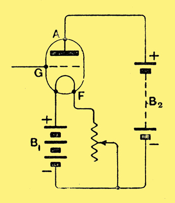
Figure 3.
The introduction of the grid between the filament and the anode greatly affects the flow of electrons through the valve. If a battery, B2, is connected between the grid and the filament in such a way as to make the grid negative to the filament (Fig. 4), it will tend to drive the emitted electrons back into the filament.
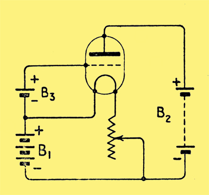
Figure 4.
Reversing the connections of the battery so that the grid is now positive to the filament, the grid no longer repels the electrons, but permits them to flow readily through the grid spacing towards the anode.
The particular negative voltage which has to be applied to the grid in order entirely to prevent the flow of electrons depends upon the closeness of the spiral of wire forming the grid and upon the voltage applied to the anode. When the adjustments are such that no electrons are passing from the filament to the anode - the valve is said to be at extinction point, that is to say, the electron flow is extinguished (cut-off). The maximum electron flow through any given valve is determined by the rate at which the heated filament can emit electrons, and when this maximum flow is attained the valve is said to be saturated.
Between the two extremes of extinction and saturation the increase in the rate of electron flow is by no means uniform, and, in the practical example of a modern. three-electrode valve, the rate of flow is controlled by the potential of the grid.
Very important points, perhaps the most important, concerning the action of the valve are, firstly, that the potential of the grid with respect to the filament controls the flow of electrons through the valve, and secondly, that when a valve is in correct adjustment, a small change of grid potential produces a large change of anode current.
The practical function of valves in connection with wireless receiving apparatus is as amplifiers, high frequency or low frequency, and detectors or rectifiers.
Whatever type of detector is employed in a receiving set, a certain minimum amount of electrical energy must be available before such detector can work properly. Thus, for the reception of long distance telegraphy or telephony signals the incoming oscillatory current must be amplified by means of a valve before being passed along to the detector.
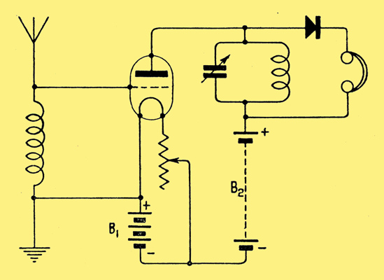
Figure 5.
In the diagram (Fig. 5) is shown a typical arrangement in which the valve acts as a high-frequency amplifier, followed by a crystal detector. This particular diagram shows a tuned anode circuit, but, of course, I am not concerned just now with the circuit arrangement so much as with the action of the valve itself. In this particular case we have oscillatory current in the aerial circuit (which, of course, is in resonance with the distant transmitting station), applied to the grid and filament of the valve. The oscillatory current, it should be remembered, is at radio-frequency, that is to say, for a 300-metre wave the frequency is 1,000,000 per second. Now, remembering the two important rules which I mention, namely (1) The potential of the grid controls the flow, of electrons - through the valve, and (2) when the valve is correctly adjusted a small change of grid potential causes a large change in anode current, it will be seen that oscillatory current of the same frequency, but of greater amplitude, will be set up in the anode circuit which, in this case, is tuned to that frequency. Across the capacitor in the tuned anode circuit, therefore, will be set up comparatively high potentials, and these, of course, are available for operating the crystal detector and telephone receivers. As the action in the valve is entirely electrical, that is to say, there are no mechanical moving parts possessing inertia, the valve is able to respond accurately to frequency variations as high as 10,000,000 or more per second.
Next consider the case where signals are received upon a valve or crystal detector, but it is desired to amplify them in order, for instance, to operate a loud speaking telephone.
In this case we are not dealing with oscillatory currents, but with unidirectional impulses after having passed the crystal detector. These unidirectional impulses are applied to the grid and filament of the amplifying valve, and, by a cumulative action, vary in potential with respect to the filament, thus giving rise to amplified impulses of current in the anode circuit, in which circuit are now placed the telephone receivers.
I now come to the last of the three functions of the valve which I mentioned earlier, namely rectification. In Fig. 6 is shown a typical detector valve arrangement to assist in the explanation.
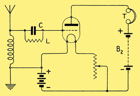
Figure 6.
I give a simple single circuit receiver with valve detector, and the usual high resistance telephone receivers included in the anode circuit. Here the differences of potentials existing between the ends of the aerial tuning inductance are applied to the grid and filament, the connection to the former being made through a small capacitor (C) known as the grid capacitor, which in turn is shunted by a high resistance L, or leak, having a value of about 2 megohms (2,000,000 ohms). Note particularly that in this instance the lower end of the aerial tuning inductance is connected to the positive side of the filament. Under these conditions the grid will have a slightly positive potential to the filament, and quite an appreciable steady anode current will be flowing. The grid capacitor affords an easy path for oscillatory currents, but any direct current flow from the grid must take place via the two-megohm grid leak. During the arrival of signals, the opposite ends of the aerial tuning inductance are made alternately positive and negative. The grid, therefore, will become alternately positive and negative to the filament. Each time-the grid is made positive, it intercepts and collects electrons on their way from the filament to the anode. Each negative half wave produces no effect upon the grid other than to make it momentarily more negative. As the negative charge accumulating upon the grid cannot readily escape owing to the high resistance leak, it follows that the total effect of an incoming signal (for instance a group of waves from a spark transmitting station) is to cause one steady reduction of anode-telephone current. In the modern hard valve (by hard is meant a valve having a very good vacuum), there is no sharply defined critical point, as in the case of a crystal detector for instance, and it is necessary to employ the grid capacitor and leak method of rectification. It is to be noted, however, that when this method is employed, actual signals in the telephone receivers are due to a reduction of anode current.
Upon the cessation of incoming signals (say in the interval between wave trains), the negative charge upon the grid leaks away, and the grid resumes its normal average potential in readiness for the arrival of the next signal. My remarks would be scarcely complete if I did not refer to the well-known circuit arrangement in which the receiving detector valve may be made to act as a feeble generator of continuous oscillations (with disastrous effects upon the tempers of the owners of adjacent receiving stations if employed during broadcast hours).
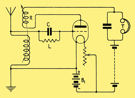
Figure 7.
In the arrangement shown in Fig. 7 the second coil, which is lettered R, and known as the reaction coil, is included in the anode circuit of the valve, and inductively coupled to the ATI in such a direction that energy from the anode circuit is passed back again into the grid circuit, where it undergoes further amplification.
When the direction of the winding of the respective coils is correct and the coupling is sufficiently tight, the natural loss of energy which occurs in the aerial circuit is more than compensated for by the additional energy from the anode circuit, and the aerial circuit is maintained in a state of continuous oscillation.
Referring, to the circuit diagram (Fig. 7), that of a self-oscillating receiver, I need scarcely mention that such an arrangement is not permitted upon the broadcast wavelength during broadcasting hours.
|