|
Significance of the Two Systems in Power Supplies
Among requests received from readers is one for an explanation of the why and wherefore of swinging chokes. Resisting the temptation to invent an analogy between them and swinging cats (or even pirates) I will go straight into a comparison between the two diagrams presented below.
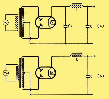
Two alternative types of full-wave rectifier circuit (a) capacitor input, and (b) choke input.
A period of 15 seconds is allowed for reaching the conclusion that they both represent full-wave rectifier circuits, and that (b) is exactly the same as (a) except that CR is missing. Those who are not well up in the design of such circuits might suppose that the only real difference was that the DC output from (b) was less well smoothed; a deficiency which could probably be made up by increasing the capacitance of C, and certainly by adding another choke-and-capacitor filter stage. Actually, however, the two circuits work on entirely different principles and have different characteristics. In particular, the choke L in (b) has to be of a special kind, commonly known as a swinging choke, quite different from the one in (a).
Circuit (a) is the arrangement commonly used for supplying HT current to small power amplifiers, etc., from an AC supply. CR acts as a reservoir. If no current is being drawn off it charges up during the first few cycles to the peak voltage of each half of the transformer secondary coil. This state is illustrated in (a) below, which covers one complete AC cycle. Current cannot be shown on this diagram because there is none going either in or out.
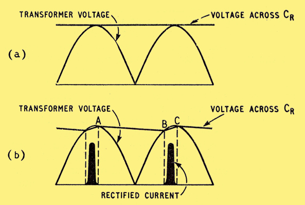
Diagrams showing the working conditions of a capacitor-input circuit, when (a) there is no current, and (b) load current is being taken.
When current is drawn by a load it starts to discharge CR, as indicated by the downward slope from A to B in (b). CR can only recharge when the transformer voltage rises above its own voltage, thereby providing a small balance to drive current through whichever half of the rectifier is receiving it. During this phase, marked B to C, CR has to receive enough current to keep the load supplied continuously throughout half a cycle.
This is where the designer is faced with a dilemma. If he makes CR small it will lose voltage rapidly between AC peaks, the result being a much lower average output voltage at full load than at no load. In technical language, it has bad regulation. It follows too that there is a very large ripple on the output voltage, necessitating much smoothing. If on the other hand he makes CR large enough to hold the output voltage well up, B comes nearly to the voltage peak, so the period represented by BC is only a small fraction of the half-cycle (AC) and the peak current through the rectifier is therefore many times greater than the steady load current. This is bad for the rectifier, unless an abnormally large sized one is used. It is also bad for the transformer, unless a large and expensive model is used, because a pulse waveform has a much greater RMS value which is what counts in heating the windings than the mean value, which is the useful output.
One puts up with these inconveniences when the amount of power to be supplied is so small that the extra cost of the components is not worth seriously bothering about, and especially when the load current is fairly constant, as it is for example when it consists of a Class A amplifier. The current peak can if necessary be kept within reasonable bounds by means of a resistor in series with the rectifier. And the system does have the advantage that the output voltage can be a fairly high percentage of the peak input voltage.
But for large power amplifiers, say 50 Watts or more, the extra cost of the rectifiers and transformer on account of the highly peaked current waveform is serious. What is perhaps more serious is that high-power amplifiers often work in Class B (or C), so the current drawn is liable to fluctuate between wide limits. The steep fall-off in output voltage when the current drawn increases, in short, the bad regulation is then a most undesirable feature of this capacitance-input power supply system.
Compare the choke-input system, (b) in the top diagram. Let us suppose that the inductance, L, of the choke is large enough to keep the current through it practically constant. Then the output voltage across the smoothing capacitor C must be practically constant and can be represented by a horizontal straight line. On the rectifier side of the choke the voltage (neglecting the loss of volts in the rectifier when it is conducting) consists of the half-cycles seen in the second diagram. So the voltage across the choke must be the difference between these semi-sinewaves and the constant voltage. The question is, how high up in the diagram below must we draw the horizontal line to represent the constant output voltage?
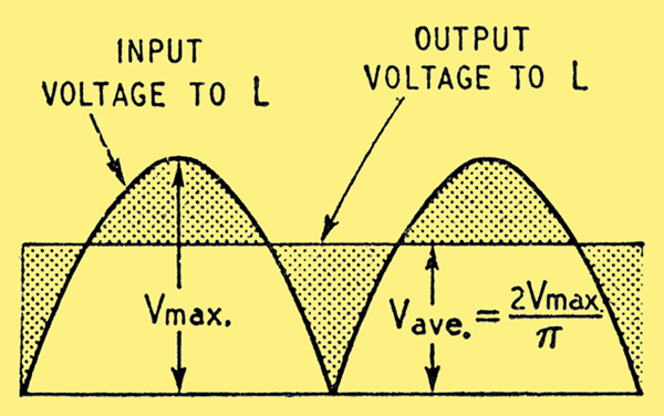
Approximate voltage relationships in a choke-input circuit with very large choke inductance, when some current is flowing.
If we neglect the resistance of the choke and assume it is purely inductive, the voltage across it must be entirely alternating, with no DC component. This means that its average each side of its zero line is equal. The horizontal output-voltage line can be regarded as the zero line for the choke voltage, which is then represented by the half-cycle wave-form above and below it. To be purely alternating, the shaded areas below the line must be equal to those above. This is the same thing as saying that the height of the horizontal line must be equal to the average height of the half-cycle waveform. The books show us that this height is 2/π or 0.64 times the peak height, which we call Vmax.
Since we know that the voltage across an inductance L is equal to L times the rate at which the current through it is changing, we can find the current wave-form. Its slope at any point must be proportional to the shaded voltage, so is something like the diagram below.

Waveform of ripple current corresponding to the voltage waveform in the previous diagram.
At this stage you may object that we were supposed to assume a constant output current and here I am showing it varying. I would point out however that we assumed it was practically constant, which means that any variation is small. So the diagram represents a small ripple on a relatively large constant current. There must be some ripple, to generate the shaded voltage across L.
With our simplifying assumptions the output voltage is as shown above, regardless of the amount of DC drawn by the load. So the choke voltage, and therefore the current ripple needed to induce it, is the same at all load currents. In practice an increase in load current does drop the output voltage slightly, because it has to pass through the neglected resistances of choke, rectifier and transformer. Provided these are kept low, the output voltage re mains steady at nearly 0.64 times the peak value over a wide range of output current, instead of varying steeply as in the capacitor-input system.
In practice, L cannot be so enormous that the ripple current is negligible. It may be fairly small compared with full load current, but if the load current is reduced sufficiently a point will be reached where it is not as big as the ripple, so current will cease altogether at the troughs of the ripple. During these periods of interrupted current (twice per AC cycle) L obviously cannot give rise to any voltage whatsoever and our theory breaks down. In the limit, when there is no load current at all, L might as well not be there, and C tends to take the place of CR in the first diagram (a), so that voltage across it builds up to the peak level.
The relationships between output voltage and load current therefore work out as in the next diagram, where (a) is the capacitor-input curve and (b) the choke input. The 'critical load' for (b) is the load current which is only just enough to be continuous in spite of the ripple. At smaller load currents the output voltage soars up towards peak value, and at larger currents it falls gradually owing to the resistance of the rectifier, etc. The steeper fall of (a) is because of the effect explained in connection with the second diagram. One of the objectionable features of (a) is that if current is not being drawn, for example, while valves are warming up, the voltage rises about 40% above its full-load level, so all the components concerned have to be rated accordingly. The choke-input system can be freed from this disadvantage if its load current is never allowed to fall below the critical point. This can be ensured by a suitable resistor connected in parallel with C and known rather unpleasantly as a bleeder. Such a device would be wasteful if the current taken by it, at least equal to the critical load current, was not small compared with the full load current; say at most a tenth and preferably less than that. So the requirement for L is that it must be large enough for the critical load current to be of this order.
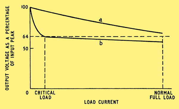
Comparison of output voltage/current curves for (a) capacitor input and (b) choke input systems.
An approximate calculation, given at the end, in case anyone is interested, shows that the critical inductance, which is the minimum inductance needed to ensure continuity of current, and which we will call Lc, is equal to the critical load resistance (Rc) divided by 6πf, where f is the supply frequency to the full-wave rectifier. At f = 50 this reduces to Lc = Rc/940. To take an example, suppose the output voltage (at the critical load) is 500, and one doesnt want the critical load to be more than 10mA. Then Rc = 500/10 = 50kΩ. Assuming f = 50 Hz, Lc = 50,000/940 = 53 Henries. If the full load current is something like 150 or 200mA, that is a formidable inductance to provide, especially if (in order to realize the benefits of the system) its resistance has to be kept low.
Fortunately, however, there is no need for its inductance to be anything like 53H at full load. 5H would be more than enough to ensure continuity of current. In the capacitor-input system, the important thing is to ensure adequate smoothing inductance at full load current, and to avoid saturation of the choke core a gap must be left in it, which necessitates more turns to keep up the inductance and therefore more resistance or higher cost. But the choke in the choke-input system can be allowed to saturate quite a lot at full load provided it gives a high inductance at critical load. I am not certain of the origin of the description 'swinging' for this kind of choke, which was used at least as far back as 1929, but apparently it refers to the variation of inductance when the DC through it is varied.
That is not the only difference between it and the ordinary smoothing choke. The third diagram shows that the peak voltage across it at all working load currents is about equal to the full output voltage. So the insulation of the windings must be adequate. One way in which the critical current can be reduced (or alternatively the critical inductance reduced) is to tune the choke to the fundamental ripple frequency, which is twice the supply frequency. This is done by connecting a suitable capacitor across L. Admittedly it by-passes the higher ripple frequencies, but they can easily be dealt with by the subsequent smoothing filter. Suppose in the previous example we cut down the 10mA inductance of the choke to 20H. This alone would not provide enough impedance at 100 Hz to keep the fundamental ripple current below 10mA peak, but it could be made to do so by means of about 0.127μF in parallel with it.
The rectifier used in conjunction with choke-input is usually a gas-filled type, because that has negligible slope resistance and so promotes the constancy of output voltage. The absence of current peaks much greater than the full load current means that quite a small rectifier can handle considerable power. Unless some historian can prove the contrary, it may be taken that choke-input was introduced specifically to enable the best use to be made of the then new gas-filled rectifier.
Summarizing
The capacitor-input system gives bad regulation and requires higher rated transformer, rectifier and smoothing capacitors than choke-input. In low-power apparatus, especially for more or less constant load current, these disadvantages, being small, may be outweighed by the advantage of higher output voltage. The greater the power to be supplied the more likely the choke-input system is to show an overall economy, and for Class B and similar requirements it is far the better. The choke must have a low resistance and a high inductance at low current, and be capable of standing peak voltages of the same order as the maximum output voltage. It is helpful to tune it by parallel capacitance to minimize the critical load current, below which the output voltage rises very steeply.
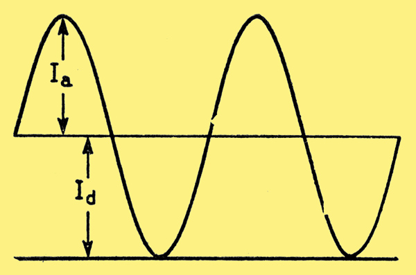
Fundamental ripple and load currents at the critical point.
Lastly, here is the derivation of the Lc = Rc/6πf formula. In the diagram above, Id is the DC or load current and Ia is the peak ripple current at its fundamental frequency, which is 2f. At the critical value of Id it is equal to Ia. Denote the peak alternating voltage by Vmax assuming sine waveform, its average value is 2Vmax/π. The load current Id is equal to this divided by the total DC resistance, of load plus choke, rectifier and transformer. At the critical Id these additions are normally small enough to neglect compared with the critical load resistance Rc, so critical Id ≈ Vmax/πRc.
Now the peak alternating component of the full-wave rectified 'input voltage to L' in diagram three, at its lowest frequency (which is 2f, the fundamental ripple frequency) is 4Vmax/3π. Again neglecting the rectifier etc. resistance, and also the impedance of C at that frequency, we have Ia ≈ 4Vmax/3πXL, where XL is the reactance of the choke at frequency 2f, so is 4πfL.
Putting Id = Ia, which is the critical condition: (4Vmax)/(3π x 4πfLc) = 2Vmax/πRc which simplifies to Lc = Rc/6πf.
|